14: Maintenance
PRC1099A-MS 14-27
14.7.4 PA Board
To adjust the amplifier stage bias current: turn R24 and R19 fully CCW
(counter clockwise). Monitor the +12 VDC current into the module. Set the
driver bias current to 165 mA by adjusting R19. Using R24, slowly increase
the (final bias) current by 85 mA until you obtain a total reading of 250 mA.
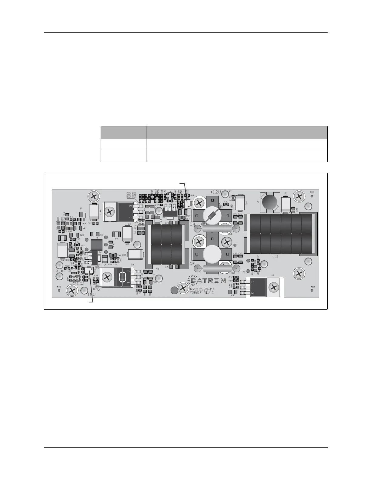
Table 14-7 provides a summary of PA board adjustments. Figure 14-10
provides signal input/output points and adjustments.
Table 14-7 PA Board Adjustments
Designator Adjustment
R19 Sets the driver stage bias level.
R24 Sets the final amplifier stage bias level.
Figure 14-10 PA Board Signal Connections and Adjustment Points