3: Audio/Filter Board
3-8 PRC1099A-MS
3.1.6 Specifications
Note: These specifications are subject to change without notice or
obligation.
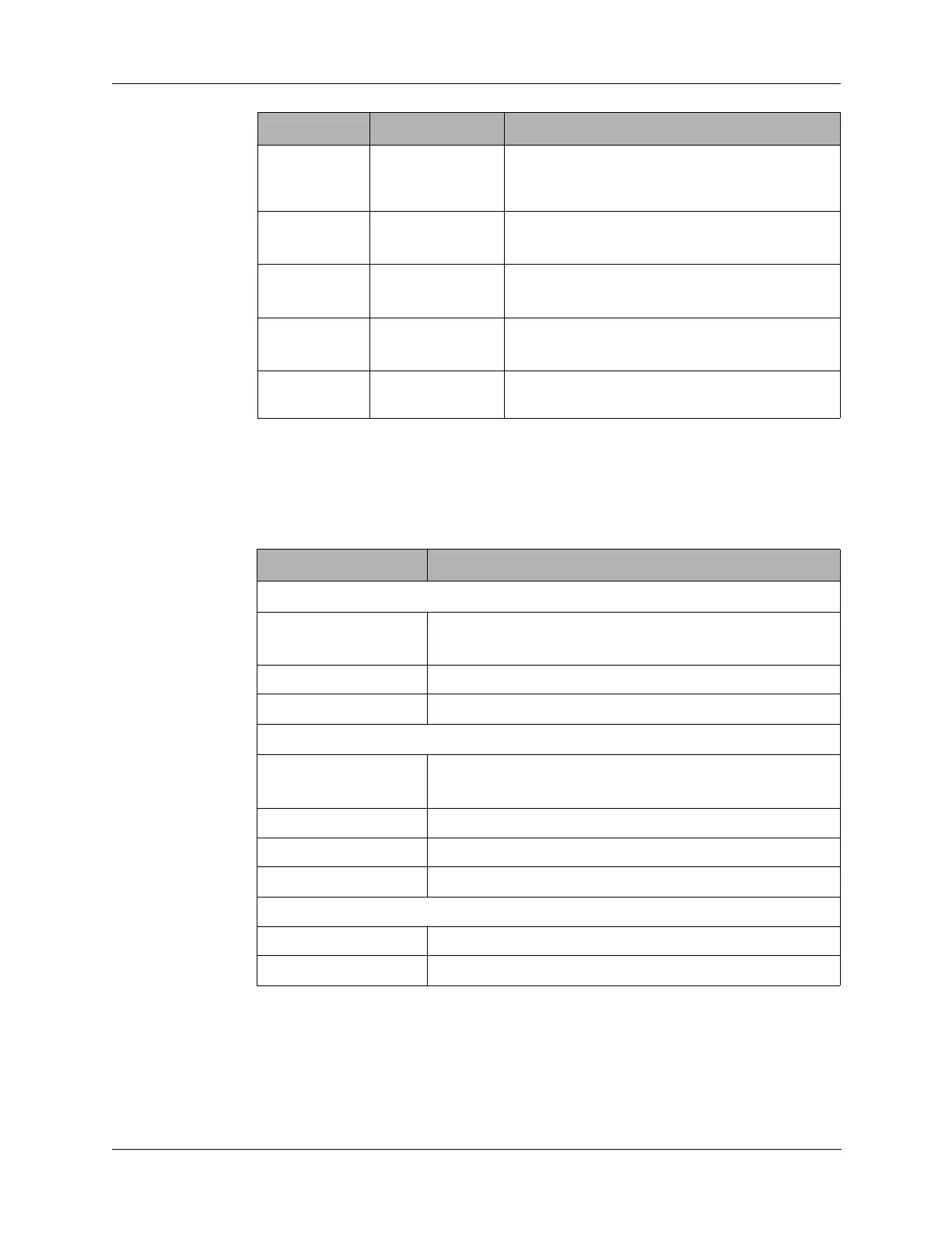
Q4 (pin 7) Normal: low
Active: high
Turns on Q20 that activates the AME selection
function on the Mixer board (refer to “AME
Option” on page 5-6).
Q5 (pin 14) Normal:
Active:
Energizes the transmitter and the CW
oscillator.
Q6 (pin 13) Normal: high
Active: low
Not used.
Q7 (pin 12) Normal: low
Active: high
Grounds the receive audio output from
product detector U4 through Q5.
Q8 (pin 11) Normal: low
Active: high
Grounds the modulated transmit line from
balanced modulator U6 through Q7.
Output State Function
Table 3-1 Audio/Filter Board Specifications
Characteristic Specifications
Transmit
Current 8 VDC at 31 mA
12 VDC at 0 mA (see Note 1 below)
Output: 1650 kHz, DSB, 80 mV, PEP
Input Microphone or 1000 Hz
Receive
Current 8 VDC at 8 mA
12 VDC at 0 mA (squelched) (see Note 2 below)
Output 1000 Hz
Input 1651 kHz
System Gain 48 dB
Low-Pass Filters
Return Loss 15 dB, minimum
Stopband Filter adjusted for specified stopband with frequencies.