3: Audio/Filter Board
PRC1099A-MS 3-9
3.2 Connector Pin Assignments
This section includes the pin assignments for all the major connectors on the
Audio/Filter board.
3.2.1 J1 Connector
J1 connects to J1 on the Processor board.
Ranges
Ranges (continued)
Note 1: Momentary high +12 VDC current during relay switching.
Note 2: Current increases with high audio output into low impedance loads.
Table 3-1 Audio/Filter Board Specifications (continued)
Characteristic Specifications
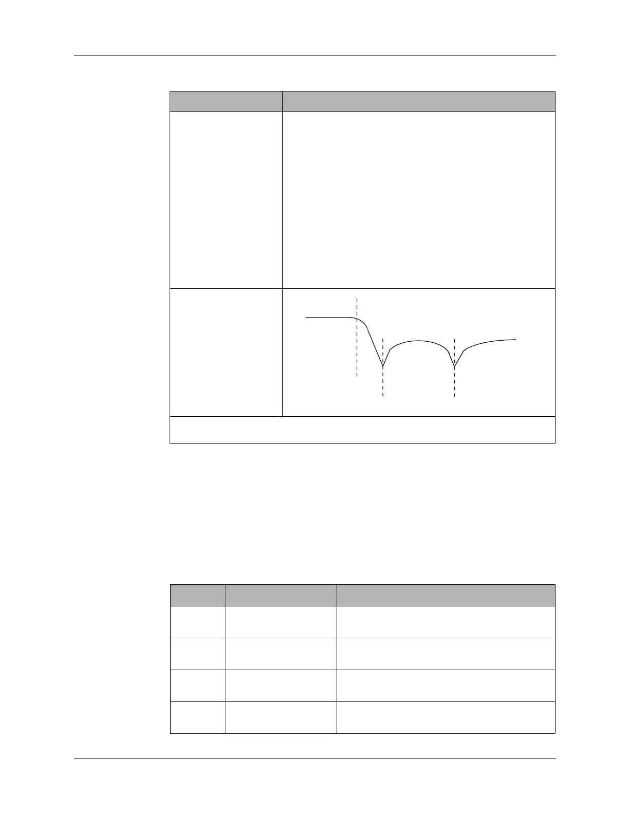
Range Notch 1 Notch 2
2.0–2.99999 MHz 4.2 MHz 6.1 MHz
3.0–4.99999 MHz 6.6 MHz 9.9 MHz
5.0–7.99999 MHz 10.8 MHz 16.35 MHz
8.0–12.99999 MHz 17.2 MHz 27.0 MHz
13.0–19.99999 MHz 27.6 MHz 43.0 MHz
20.0–30.0 MHz 40.5 MHz 60.4 MHz
FF
F
Cutoff
Passband
Stopband
Notch 1
Notch 2
Table 3-2 J1 Connector Pin Assignments
Pin Signal Description
1 ENM6C No connection on Audio/Filter board.
Jumpered to J4 pin 7.
2 ENM6B No connection on Audio/Filter board.
Jumpered to J4 pin 8.
3 ENM6A No connection on Audio/Filter board.
Jumpered to J4 pin 9.
4 ENM5 No connection on Audio/Filter board.
Jumpered to J4 pin 10.