3: Audio/Filter Board
3-10 PRC1099A-MS
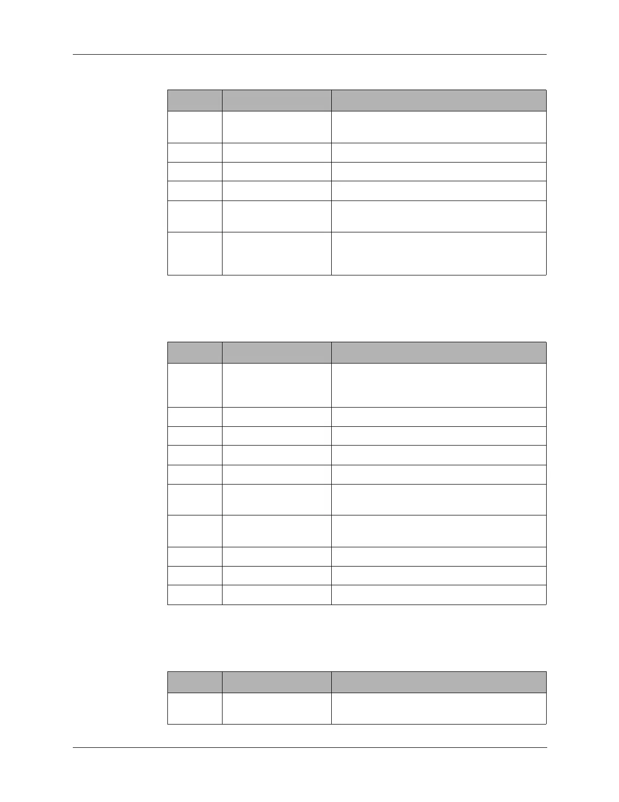
3.2.2 J2 Connector
J2 connects to J2 on the Processor board.
3.2.3 J3 Connector
J3 connects to J3 on the Processor board.
5 COMP No connection on Audio/Filter board.
Jumpered to J5 pin 9.
6 GND Ground
7 GND Ground
8 LOWPWR Connects to Audio/Filter board J4 pin 10 only
9 ALC Automatic level control, sets output power
level in transmit
10 AGC No connection on the Audio/Filter board.
Jumpered from the Processor board to the
Mixer and Junction board (J5 pin 8).
Table 3-2 J1 Connector Pin Assignments (continued)
Pin Signal Description
Table 3-3 J2 Connector Pin Assignments
Pin Signal Description
1 BITE No connection on the Audio/Filter board.
Jumpered from the Processor board to the
Synthesizer board (J4 pin 1).
2 CLOCK Internal processor clock information.
3 DATA Internal processor data information.
4 PTT Switches the radio to transmit mode.
5 +8V +8 VDC supply voltage to Processor board.
6 R8 +8 VDC in receive only, supplied to
Processor board.
7 T8 +8 VDC in transmit only, supplied to
Processor board.
8 +12V +12 VDC supply voltage to Processor board.
9 +5V +5 VDC supply voltage to Processor board.
10 +5V +5 VDC supply voltage to Processor board.
Table 3-4 J3 Connector Pin Assignments
Pin Signal Description
1 RF DET RF detect, informs microprocessor of output
power.