3: Audio/Filter Board
PRC1099A-MS 3-11
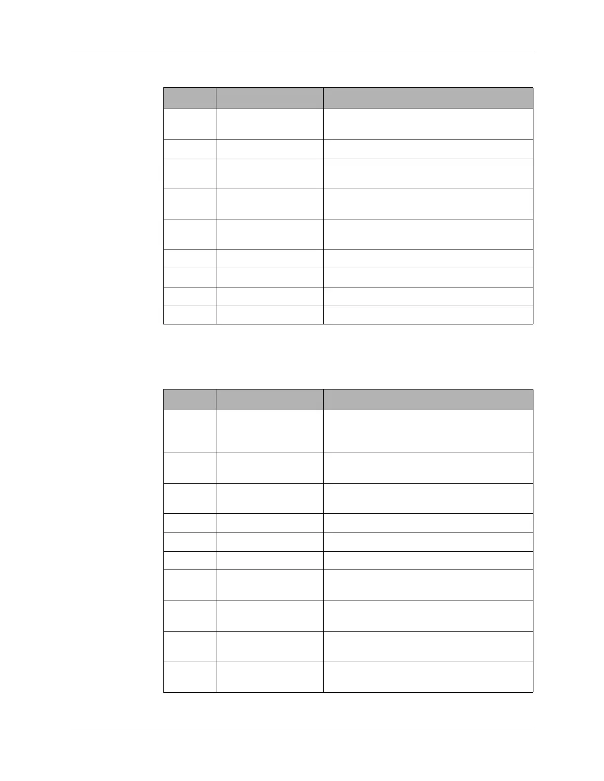
3.2.4 J4 Connector
J4 connects to the Mixer and Synthesizer boards.
2 VOICE DET Voice detect informs microprocessor of
received human speech.
3 ENM1 Enable pulse enables U7 and U9.
4 MUTE Low going pulse from microprocessor to
disable receive audio.
5 CONTRAST Output to Display board to set display
contrast.
6 CW KEY A signal from outside radio to key transmitter
as well as energize CW oscillator.
7 SPARE2 Not used.
8 600 OHM RX AUDIO Receive audio output to microprocessor.
9 SPARE1 Not used.
10 600 OHM TX AUDIO Transmit audio input from microprocessor.
Table 3-4 J3 Connector Pin Assignments (continued)
Pin Signal Description
Table 3-5 J4 Connector Pin Assignments
Pin Signal Description
1 BITE No connection on the Audio/Filter board.
Jumpered from the Processor board (J2 pin
1) to the Synthesizer board.
2 SQUELCH Output to Mixer board to disable the receive
audio.
3 AME SEL Amplitude modulation equivalent output to
Mixer board.
4 DATA Microprocessor data output to rest of radio.
5 CLOCK Microprocessor clock output to rest of radio.
6 ALC Automatic level control output to Mixer board.
7 ENM6C Output enable pulses from microprocessor to
Synthesizer board.
8 ENM6B Output enable pulses from microprocessor to
Synthesizer board.
9 ENM6A Output enable pulses from microprocessor to
Synthesizer board.
10 LOWPWR Input from PA board to automatically switch
to low power, when PA board overheats.