3: Audio/Filter Board
3-12 PRC1099A-MS
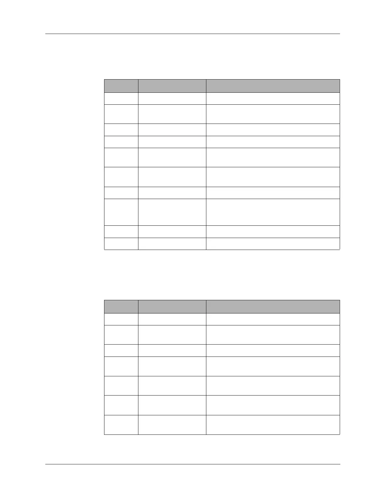
3.2.5 J5 Connector
J5 connects to multiple boards with T8, R8 +8, and +5 supply voltages.
3.2.6 J6 Connector
J6 connects to the front panel Audio and Accessory connectors as well as the
front panel Volume control potentiometer.
Table 3-6 J5 Connector Pin Assignments
Pin Signal Description
1 GND Ground.
2 ANT SW Antenna switch output to Antenna Tuner
board.
3 +5V +5V input from Junction board.
4 +12V +12V input from Junction board.
5 T8 +8V supply voltage from Junction board in
transmit mode only.
6 R8 +8V supply voltage from Junction board in
receive mode only.
7 +8V +8V supply voltage from Junction board.
8 AGC No connection on the Audio/Filter board.
Jumpered from the Processor board (J1 pin
10) to the Mixer and Junction board.
9 COMP Connects to Audio/Filter board J1 pin 5 only
10 ENM5 Connects to Audio/Filter board pin 4 only
Table 3-7 J6 Connector Pin Assignments
Pin Signal Description
1 GND Transmit audio cable shield to ground.
2 50 OHM TX AUDIO Transmit audio input (microphone) from front
panel Audio connector. Coax connection.
3 GND Receive audio cable shield to ground.
4 50 OHM RX AUDIO Receive audio input (microphone) to front
panel Audio connector. Coax connection.
5 WIPER Connects to wiper of front panel Volume
control.
6 VOL HI Connects to high side of front panel Volume
control.
7 600 OHM TX AUDIO Transmit audio input from front panel
Accessory connector.