3: Audio/Filter Board
PRC1099A-MS 3-13
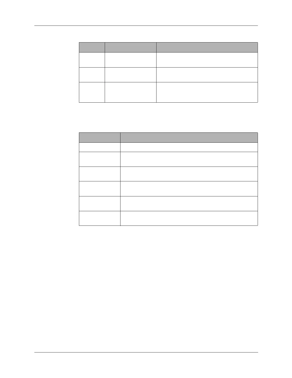
3.2.7 J7 to J12 Coax Connectors
Connector J7 to J12 are RF coax connector carrying either transmit or receive
or BFO signals as listed below.
3.3 Component Locations, Schematics, and Parts List
This section provides a component location diagram, schematic and parts list
for the Audio/Filter board.
8 GND Connects to low side of front panel Volume
control.
9 600 OHM RX AUDIO Receive audio output to front panel
Accessory connector
10 ATU TUNE Input from Accessory connector to key radio
and CW oscillator for tuning of external
equipment.
Table 3-7 J6 Connector Pin Assignments (continued)
Pin Signal Description
Connector Signal
J7 - BFO IN 1650 kHz BFO from the Synthesizer board.
J8 - RX OUT Modulated receive signal (selected channel frequency) output
to the Mixer board.
J9 - RX IN Modulated receive signal (1650 kHz) input from the 1650 kHz
IF board.
J10 - TX OUT Modulated transmit signal (1650 kHz) output to 1650 kHz IF
board.
J11 - RF IN 5/20W modulated transmit signal (selected channel frequency)
input from the PA board.
J12 - RF OUT Transmit: 5/20W modulated transmit signal (selected channel
frequency) to the Antenna Tuner board.