26
Specifications for the Metering inputs are:
12-bit resolution
Bipolar/Differential inputs (up to 80V common mode rejection) with 1 MΩ input impedance
Selectable input ranges of 0.5, 2.5, 5, 10, 20, 40 & 80 VDC
Jumper-selectable 4-20mA input mode
Software selectable signal rectifier on all inputs
Specifications for the Status inputs are:
Independent grounds on each input
Opto-isolated
Impedance > 22 kΩ
Detection Levels: -12 to 0.8 VDC (low), +2.4 to +12 VDC (high)
Specifications for the relays are:
70 VAC @ 0.4A, 30 VDC @ 2A, or open collector (100 mA)
Depending on your requirements and setup, you must also remember to connect the telephone line, the Power Fail
detector wall-wart, the network and most importantly, to ground the unit with an appropriate ground wire or strap.
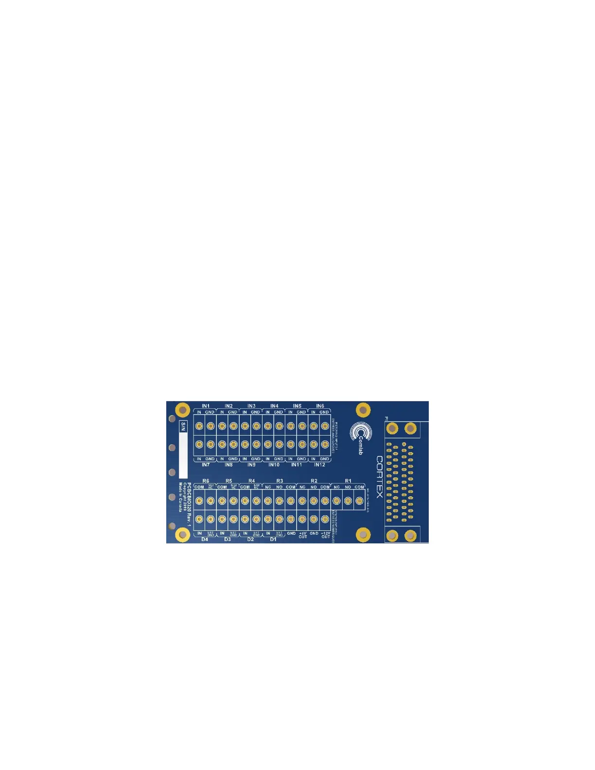
2.7.2 Connecting Physical I/O to the Cortex-320
The most convenient way to connect physical I/O to the Cortex-320 is through Davicom’s DVIO320 screw-terminal I/O board.
This board provides complete connection options for the auxiliary DC outputs (+12V and +5V), the metering inputs, the
internal or external-ground status inputs as well as the relay outputs.
The panel’s layout is shown below.
Specifications for the Metering inputs are:
12-bit resolution
Single-ended input with 1 MΩ input impedance
Selectable input ranges of 5 & 60 VDC
Audio rectifier jumper selectable on all inputs
Useable as Status Inputs also with selectable internal pull-up resistor
Specifications for the Status inputs are:
Independent grounds on each input
Opto-isolated
Impedance > 22 kΩ
Detection Levels: -12 to 0.8 VDC (low), +2.4 to +12 VDC (high)