Home
DayTronic
Measuring Instruments
4000 Series
DayTronic 4000 Series User Manual
4
of 1
of 1 rating
72 pages
Give review
Manual
Specs
To Next Page
To Next Page
To Previous Page
To Previous Page
Loading...
For transducer cabling to an optional
Model 10CJB-2 Bridge
Completion Card
, see Appendix F
.
---------- NOTE ----------
CABLE SIGNAL WIRES OR TWISTED WIRE P
AIRS
SHOULD AL
W
A
YS BE PROPERL
Y
SHIELDED
, AS INDI-
CA
TED IN THE CABLING DIAGRAMS. THIS WILL MINI-
MIZE THE PRODUCTION OF UNW
ANTED ELECTRICAL
NOISE FROM CAP
ACITIVE AND INDUCTIVE EFFECTS.
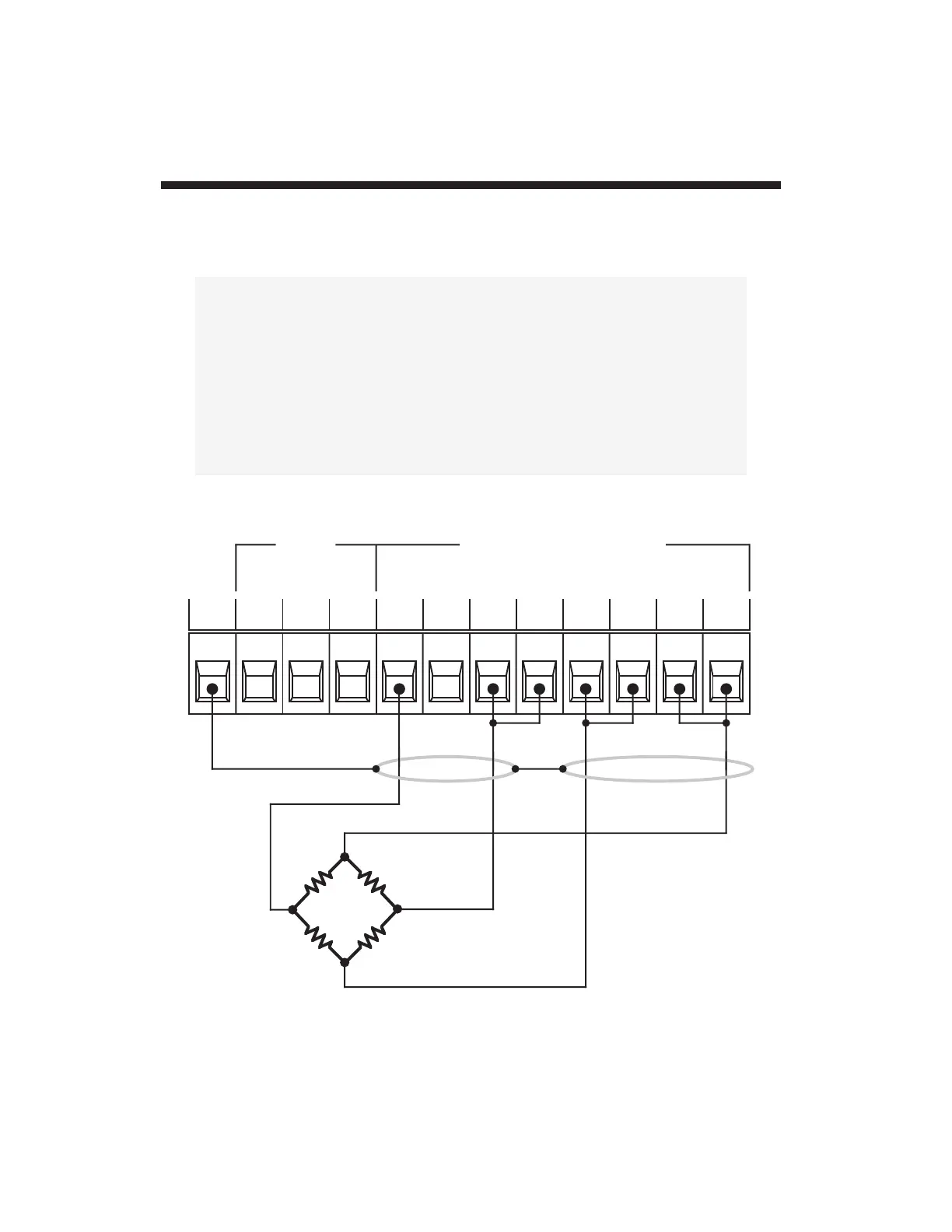
2.a
T
ransducer Cabling
2.
2
SHIELD
+SENSE
+EXCITATION
–EXCITATION
–SIGNAL
+SIGNAL
–SENSE
CAL
SENSE
PEAK
CONTROL
INPUT
– PK
IN
+ PK
IN
–
SIG
SHLD
SIG
COM
+
SIG
CAL
SENS
PWR
COM
–
SENS
–
EX
+
EX
+
SENS
STRAIN GAGE INPUT
Fig. 6(a)
4077
T
ransducer
Cabling:
4-Wire Strain
Gage Cabling
(under 20 ft. in
length)
25
27
Table of Contents
Table of Contents
5
Description and Specifications
6
Physical Layout
11
Panel Mounting
14
Standard Channel Configuration
15
Standard Logic Configuration
16
Using the Front-Panel Setup Buttons
18
Low Battery Warning
24
Transducer Cabling
25
Powerup
28
AC Operation
28
DC Operation
29
Adjusting LCD Viewing Angle
31
Selecting a Channel for Display
32
Channel Calibration
33
Setting Channel Filters
35
Scaling the Bargraph Display
36
Defining Limit Zones
37
Logic I/O Connections
38
Analog Output Connections
40
Operation: Use of Front Panel Buttons
41
Appendix B: 4077/Computer RS-232-C Connections
47
Appendix C: Legend and Indicator Annunciation
50
Appendix E: "Computed" and "Simulated" Calibration
52
Optional Model 10CJB-2 Bridge Completion Card
55
Appendix G: Analog Peak Capture
60
Appendix H: Changing the Battery
69
4
Based on 1 rating
Ask a question
Give review
Questions and Answers:
Need help?
Do you have a question about the DayTronic 4000 Series and is the answer not in the manual?
Ask a question
DayTronic 4000 Series Specifications
General
Brand
DayTronic
Model
4000 Series
Category
Measuring Instruments
Language
English
Related product manuals
DayTronic 3500 Series
122 pages

 Loading...