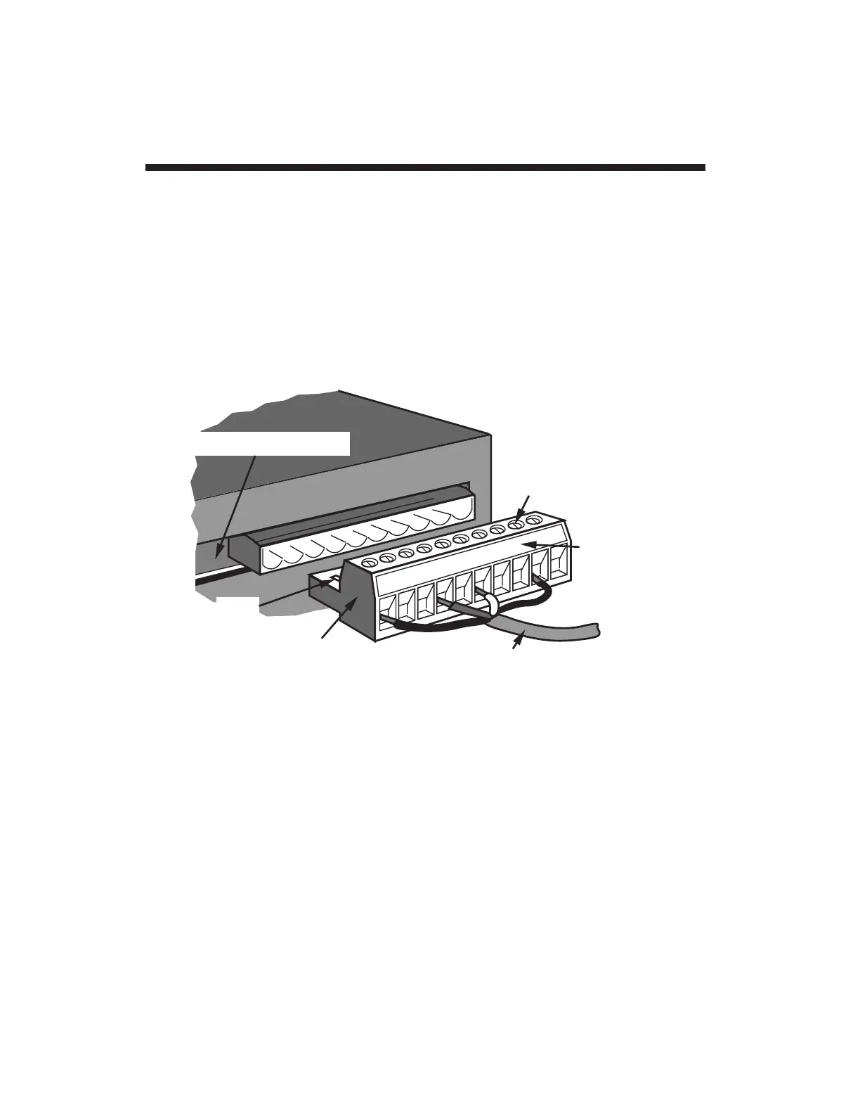
Located on the rear of the 4077, the
12
-pin ANALOG INPUT CONNEC-
TOR is similar to the 10-pin connector shown in Fig. 5. Referring to the
appropriate
cabling diagram
below, connect the wires of your TRANS-
DUCER CABLE to the corresponding screw terminals of the INPUT
CONNECTOR. To facilitate cable connection, the front (screw-terminal)
portion of the connector may be removed from the rear (pin) portion,
which is mounted on the 4077's internal ANALOG INPUT BOARD.
Press hard when reinserting the front portion, to make sure it is fully
engaged (the small clips should snap into place on the rear portion).
4-wire strain gage cabling (Fig. 6(a)) is to be used when the cable is
under 20 feet in length. In this case, the +SENSE and –SENSE lines
are tied to the corresponding EXCITATION lines, and also the CALI-
BRATION SENSE line to the +SIGNAL line,
at the CONDITIONER
CONNECTOR.
8-wire strain gage cabling (Fig. 6(b)) is to be used when the cable is 20
feet or longer. In this case, the +SENSE and –SENSE lines are tied to
the corresponding EXCITATION lines, and the CALIBRATION SENSE
line to the +SIGNAL line,
at the transducer.
Note also the wire con-
nected to the –SIGNAL line, at the transducer, but left
unconnected
at
the 4077. This wire is to be paired with the CAL SENSE, as shown, for
shielding purposes.
2.1
Transducer Cabling 2.a
 Loading...
