Your 4077 provides eight logic input/output bits in
open-collector,
negative-true
form, where the "Logic 1" state is defined as nominal
0
V-DC
and "Logic 0" as nominal
+5 V-DC.
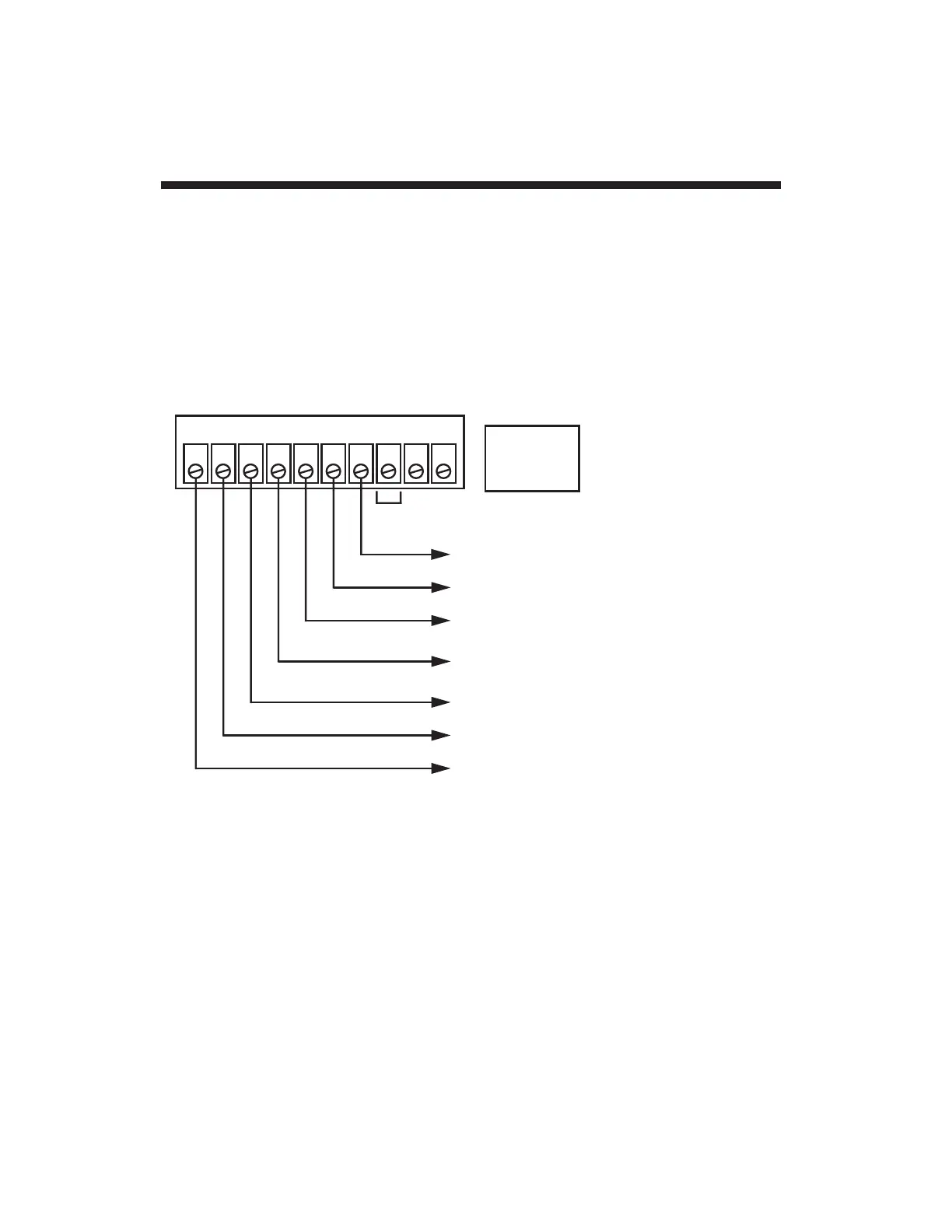
The standard logic I/O
configuration is shown in Fig. 4, below, with reference to the 10-terminal
Logic I/O Connector on the rear of the 4077. For recommended logic
interconnections, see Section 2.i.
You can use the seven logic control outputs to actuate solenoid valves,
illuminate panel displays, sound alarms, start and stop motors or
pumps, initiate and control safety shut-down sequences, and perform
many other automation tasks that require "intelligent" switching, even of
substantial amounts of power. These are
nonlatching
outputs; each
terminal will return to
Logic 0
as soon as the corresponding limit
violation ceases to occur. For "Defining Limit Zones," see Section 2.h.
1.e Standard Logic Configuration
1.11
0 1 2 3 4 5 6 7 +5 GD
LOGIC LOW
TO ENABLE
(see Fig. 9)
Unassigned
CHN. 5 IN "ABOVE BARGRAPH" ZONE
CHN. 5 IN UPPER "DANGER" ZONE
CHN. 5 IN UPPER "CAUTION" ZONE
Logic Outputs:
CHN. 5 IN SAFETY (NO VIO) ZONE
CHN. 5 IN LOWER "CAUTION" ZONE
CHN. 5 IN LOWER "DANGER" ZONE
CHN. 5 IN "BELOW BARGRAPH" ZONE

 Loading...