E – Mechanical Installation
April, 2018 E-6 INM.XX.X.00
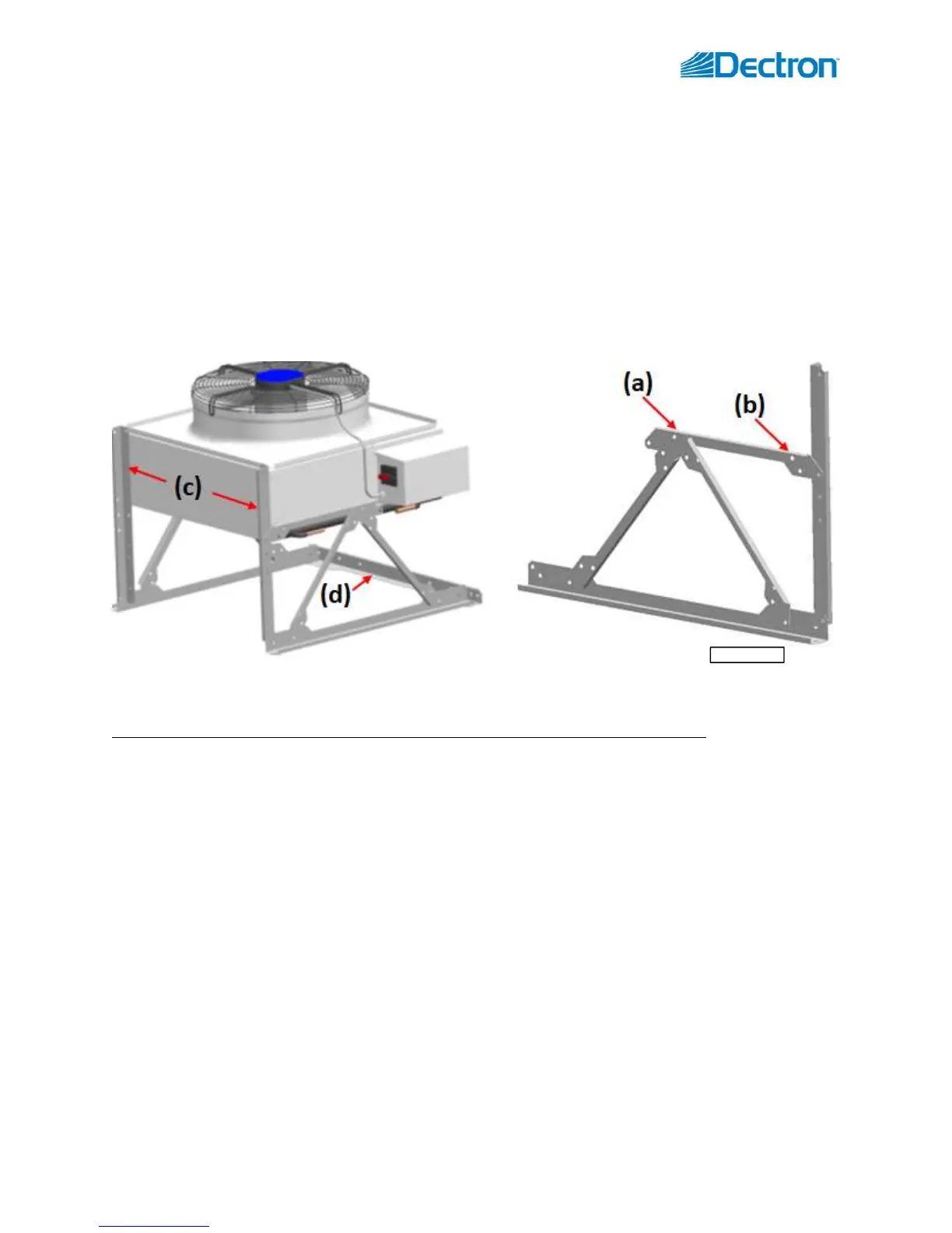
OACC model NC-B assembly is shown on Pic. E.7B below:
o Uncrate/unwrap the condenser and mounting kit.
o Assemble left and right mount legs as shown with provided bolts, nuts, and washers (except for joint
point (a) – it must be bolted to the condenser)
o Align holes (a) and (b) in the mount legs with the holes in the condenser and attach them with provided
bolts, nuts and washers.
o Attach rear support braces to the condenser with provided self-tapping screws (c)
o Install the optional front cross piece (d) between left and right leg with provided bolts, nuts and
washers;
o Ensure that the assembly is straight, square and sturdy; tighten all bolts.
o Ensure that the condenser is levelled and firm; affix mount legs footings to the surface (concrete slab,
etc.); anchors/fasteners for surface mounting are NOT included.
Horizontal airflow configuration (equipment is mounted on a vertical surface such as a wall.). In this case, use the
same mount kit as above. Note that the mount legs are assembled slightly differently.
OACC model NC-Z and NC-B and OAFC model NG-Z assembly is shown on Pic. E.7C below:
o Uncrate/unwrap the equipment and mounting kit.
o Assemble left and right mount legs as shown with provided bolts, nuts, and washers (except for joint
point (a) – it must be bolted to the condenser/cooler)
Note that the cross-piece (b), that is to be attached to the equipment, is mounted differently
for NC-Z/NG-Z and NC-B.
o Before final assembly of equipment and mount legs, ensure following:
For Outdoor Condenser NC-B: electric box is positioned as shown – horizontal, with drip
protection bend (c) at the top;
For all Outdoor Condensers (NC-Z and NC-B): refrigerant connections are on the side AND
liquid line connection (refer to condenser labels) is the bottom one, (e).
o Align respective holes in cross-piece (b) and the holes in the equipment and attach them with provided
bolts, nuts, and washers.
o Attach rear support braces to the condenser with provided self-tapping screws (d)
o Ensure that the assembly is straight, square, and sturdy; tighten all bolts.
o Ensure that the condenser is levelled and firm; affix mount legs footings to the surface (wall, etc.);
anchors/fasteners for surface mounting are NOT included.