PPM Installation Instructions
DEIF A/S Page 12 of 69
Option EF4
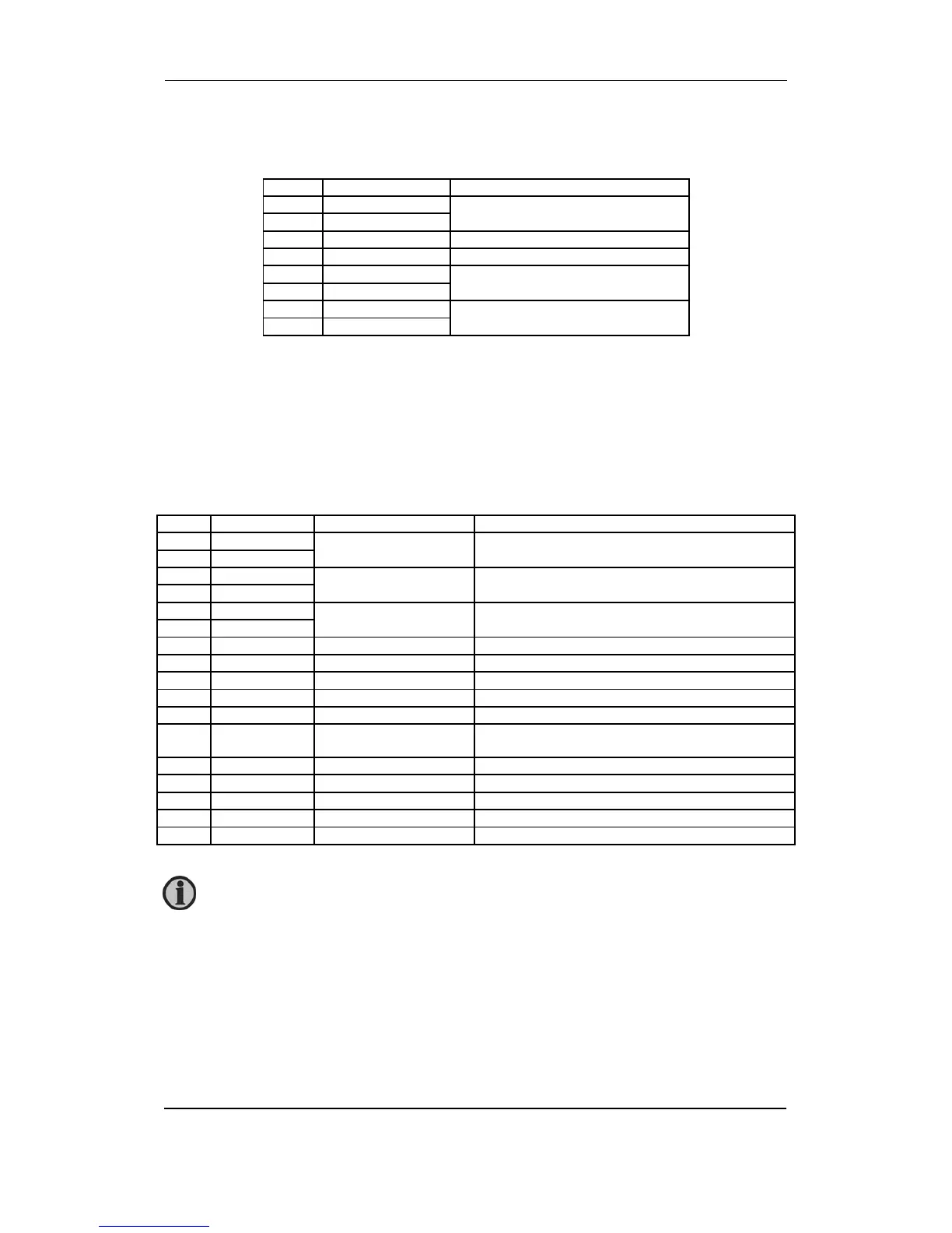
Combination output for governor and AVR (option EF4).
Term. Function Description
65 ANA + Analogue +/-20 mA for GOV or AVR
66 ANA -
67 Not used
68 Not used
69 GOV relay up Relay output for GOV or AVR
Raise speed or voltage
70 GOV relay up
71 GOV relay down Relay output for GOV or AVR
Lower speed or voltage
72 GOV relay down
In the menu system it is possible to set the speed governor to either binary or analogue output.
With option D this selection regarding AVR control is also possible.
On the PCB there is only one set of relay outputs and one analogue output. This means that if
the relay outputs are used for speed control, then the analogue output will be used for the AVR,
and vice versa.
Slot #5, AC measuring
Term. Function Technical data Description
73 I L1 s1 Generator current L1 1/5 A AC input
74 I L1 s2
75 I L2 s1 Generator current L2 1/5 A AC input
76 I L2 s2
77 I L3 s1 Generator current L3 1/5 A AC input
78 I L3 s2
79 U L1 Generator voltage L1 Max. 690V AC phase - phase value
80
Not used
81 U L2 Generator voltage L2 Max. 690V AC phase - phase value
82
Not used
83 U L3 Generator voltage L3 Max. 690V AC phase - phase value
84 U neutral Generator voltage
neutral
For land-based applications only
85 U L1 Bus voltage L1 Max. 690V AC phase - phase value
86
Not used
87 U L2 Bus voltage L2 Max. 690V AC phase - phase value
88 U neutral Bus voltage neutral For land-based applications only
89 U L3 Bus voltage L3 Max. 690V AC phase - phase value
Current inputs are galvanically separated. Max. 0.3 VA per phase. Voltage
measurements are available (phase to phase) from 100V AC to 690V AC.