PPM Installation Instructions
DEIF A/S Page 24 of 69
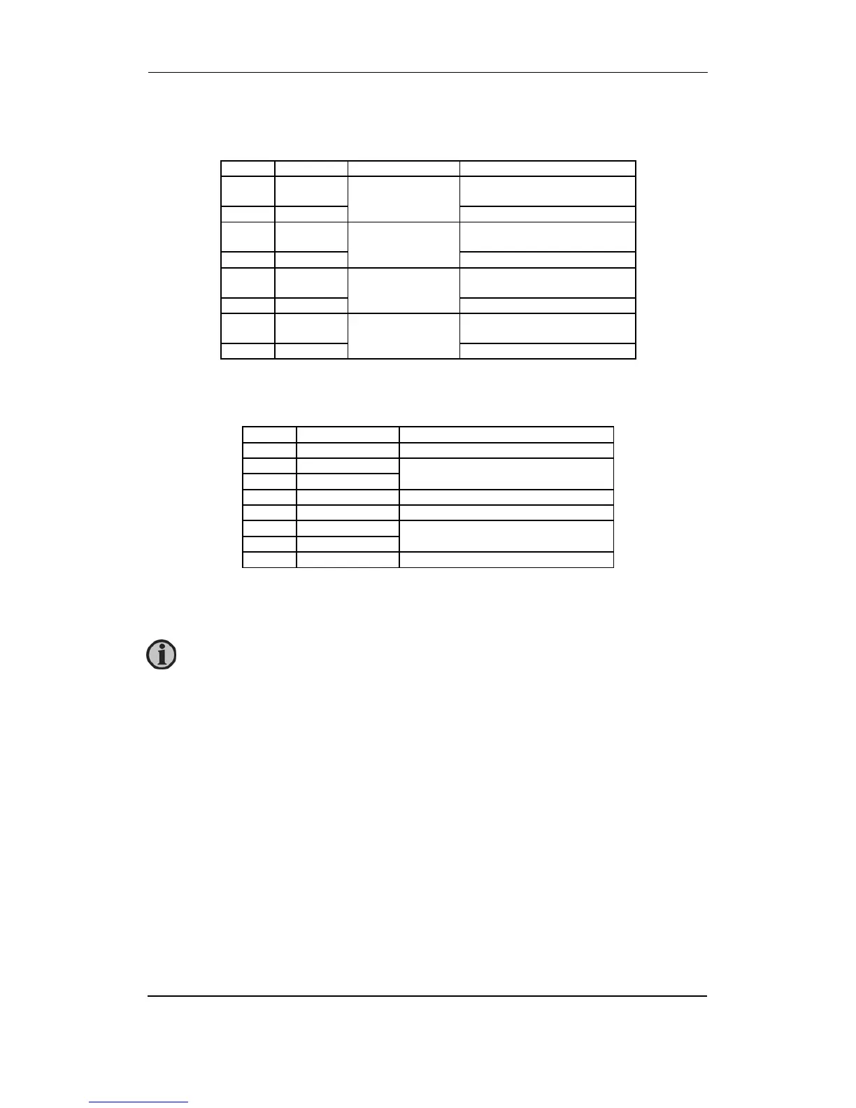
Slot #4, GOV/AVR (standard)
GOV/AVR relay output card (GOV standard) (voltage control option D).
Term. Function Technical data Description
65 NO Relay 10
250V AC, 8A
Generator GOV
Increase frequency
66 Com.
67 NO Relay 11
250V AC, 8A
Generator GOV
Decrease frequency
68 Com.
69 NO Relay 12
250V AC, 8A
Generator AVR (option D)
Increase voltage/configurable
70 Com.
71 NO Relay 13
250V AC, 8A
Generator AVR (option D)
Decrease voltage/configurable
72 Com.
Option E1
GOV/AVR analogue output card.
Term. Function Description
65 Not used
66 +/-20 mA out Speed governor setpoint output
67 0
68 Not used
69 Not used
70 +/-20 mA out AVR voltage setpoint output
71 0
72 Not used
If necessary the current outputs can be converted to voltage using a resistor across the
terminals (250 will convert the +/-20 mA into +/-5V DC).
Voltage control setpoint to AVR is an option. If a combination of analogue
signals and relay signals is needed, then option EF4 is to be used.