PPM Installation Instructions
DEIF A/S Page 25 of 69
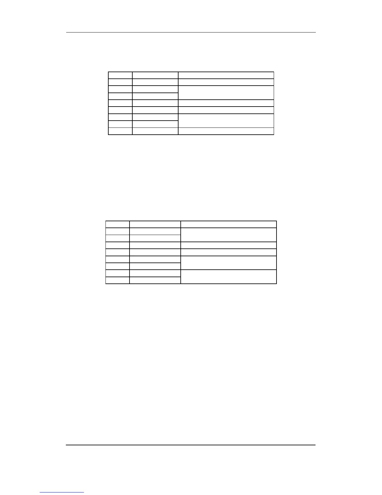
Option EF2
Analogue speed governor output and one transducer output.
Term. Function Description
65 Not used
66 +/-20 mA Speed governor setpoint output
67 0
68 Not used
69 Not used
70 0(4) - 20 mA out Analogue output 3
71 0
72 Not used
These outputs are active outputs, meaning that they have an internal power supply. The outputs
are galvanically separated from each other and from the rest of the unit. Via the display or the
PC programming software individual outputs can be selected to represent any AC measuring
value and related values, e.g. power, power factor, frequency etc. Outputs can be selected to be
either 0…20 mA or 4…20 mA in the PC utility software. If necessary the current outputs can be
converted to voltage using a resistor across the terminals (500 will convert the 0-20 mA into 0-
10V DC).
Option EF4
Combination output for governor and AVR (option EF4).
Term. Function Description
65 ANA + Analogue +/-20 mA for GOV or AVR
66 ANA -
67 Not used
68 Not used
69 GOV relay up Relay output for GOV or AVR.
Raise speed or voltage
70 GOV relay up
71 GOV relay down Relay output for GOV or AVR.
Lower speed or voltage
72 GOV relay down
In the menu system it is possible to set the speed governor to either binary or analogue output.
With option D this selection regarding AVR control is also possible.
On the PCB there is only one set of relay outputs and one analogue output. This means that if
the relay outputs are used for speed control, then the analogue output will be used for the AVR,
and vice versa.