PPM Installation Instructions
DEIF A/S Page 37 of 69
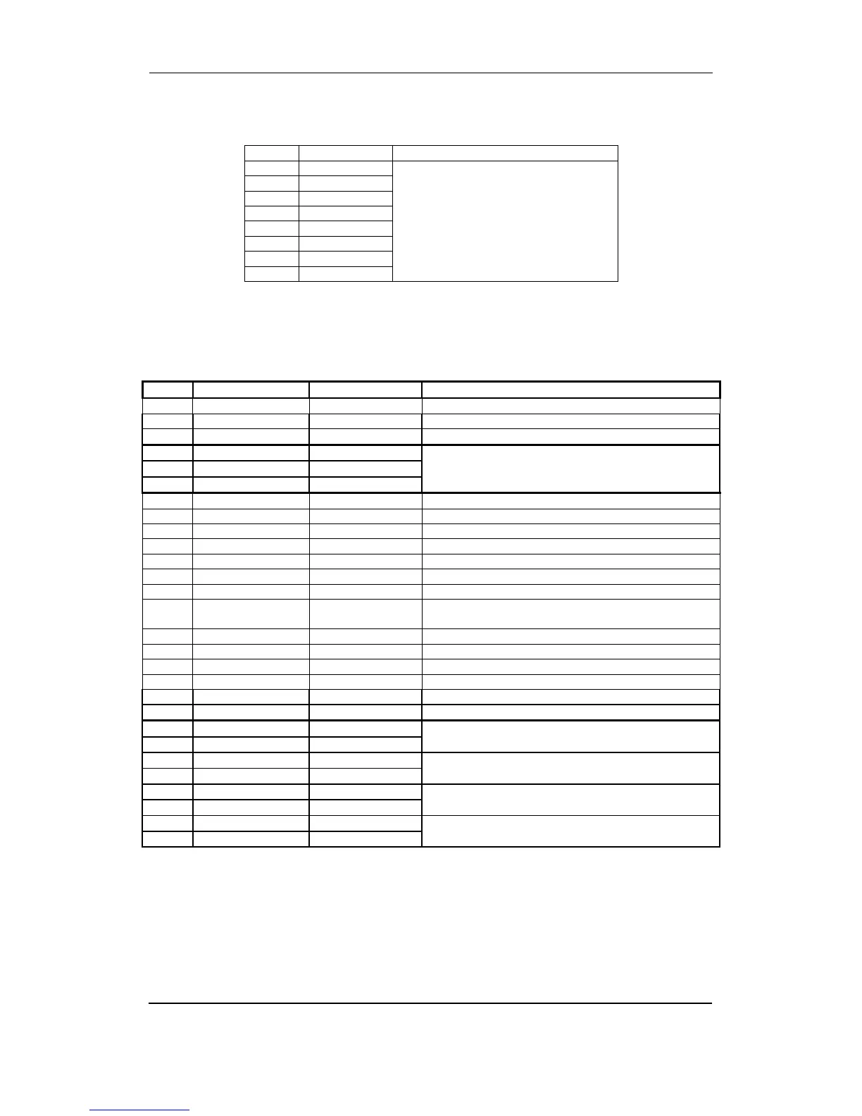
Slot #2, external communication (option)
Option H2 (RS485 Modbus RTU).
Term. Function Description
29 DATA + (A) Modbus RTU, RS485
30 Not used
31 DATA - (B)
32 Not used
33 DATA + (A)
34 Not used
35 DATA - (B)
36 Not used
The serial communication line should be terminated between DATA + and DATA - with a resistor
equal to the cable impedance.
Slot #3, binary I/O
Term. Function Technical data Description
37 -5…0…5V DC Analogue I/O Active load sharing line
38 Com. Common Common for load sharing lines
39 -5…0…5V DC Analogue I/O Reactive load sharing
40 -10…0…10V DC Analogue input
Not used
41 Com. Common
42 -10…0…10V DC Analogue input
43 Binary input Optocoupler Configurable. User-programmable
44 Binary input Optocoupler Heavy consumer 1 request/configurable
45 Binary input Optocoupler Heavy consumer 2 request/configurable
46 Binary input Optocoupler Heavy consumer 1 connected/configurable
47 Binary input Optocoupler Heavy consumer 2 connected/configurable
48 Binary input Optocoupler Heavy consumer 1 fixed load/configurable
49 Binary input Optocoupler Heavy consumer 2 fixed load/configurable
50 Binary input Optocoupler Alarm inhibit 1, external input for inhibit of selected
alarms/configurable
51 Binary input Optocoupler Selection of PTH mode/Alarm Inhibit 2
52 Binary input Optocoupler Configurable. User-programmable
53 Binary input Optocoupler Configurable. User-programmable
54 Binary input Optocoupler CB open
55 Binary input Optocoupler CB closed
56 Com. Common Common for terminals 43-55
57 NO Relay 6 Start acknowledge heavy consumer 1/configurable
58 Com. 250V AC 8A
59 NO Relay 7 Start acknowledge heavy consumer 2/configurable
60 Com. 250V AC 8A
61 NO Relay 8 Configurable. User-programmable
62 Com. 250V AC 8A
63 NO Relay 9 Configurable. User-programmable
64 Com. 250V AC 8A