PPM Installation Instructions
DEIF A/S Page 41 of 69
The engine interface board consists of configurable inputs and outputs. The configuration is
performed via the PC utility software, and the default settings can be changed to the relevant
settings. For input configuration, upload the parameter list from the unit and select the input in
question. Then a configuration dialog box will appear, and the settings can be changed. The
standard title (e.g. 4-20 mA in no. 1) can be changed, and the new title will also be shown in the
display. The minimum and maximum values of the 4-20 mA input can be adjusted:
Value: Nominal heavy consumer power (e.g. 400 kW)
Min.: Value corresponding to 4 mA (e.g. 0 kW)
Max.: Value corresponding to 20 mA (e.g. 400 kW)
The inputs can be used as high or low alarms. As a ‘high alarm’ the alarm will appear, when the
measured value is higher than the alarm limit, and as a ‘low alarm’ the alarm will appear, when
the measured value is lower than the alarm limit.
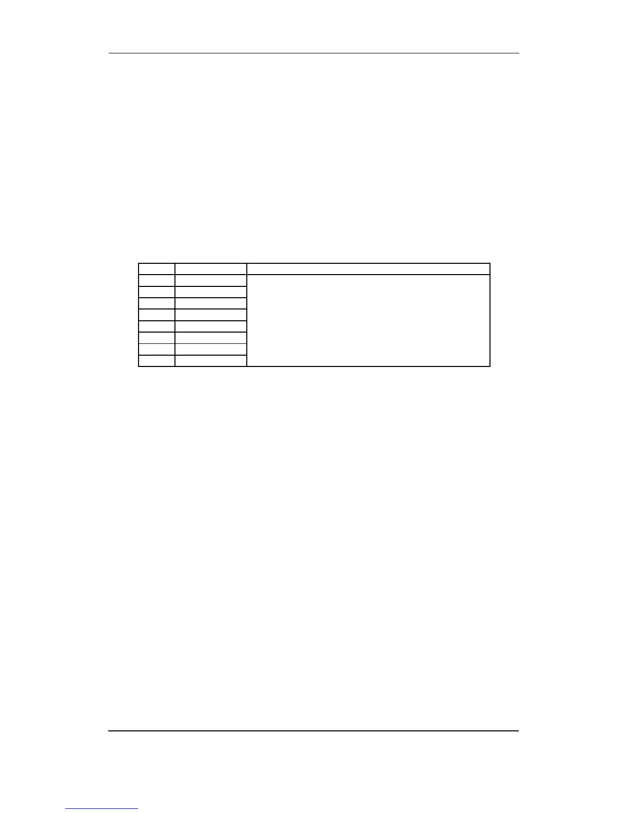
Slot #8, internal communication
Term. Function Description
126 Not used CANbus communication line between the units
For internal use only!
127 Not used
128 Can-L
129 Not used
130 Can-H
131 Can-L
132 Not used
133 Can-H