PPM Installation Instructions
DEIF A/S Page 66 of 69
Analogue inputs: -10…0…+10V DC
Not galvanically separated
Impedance: 100 k
(0)4…20 mA
Impedance: 50
Not galvanically separated
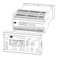
Mounting: DIN-rail mounted or base mounted with six screws. DEIF recommends
base mounting for marine applications.
If DIN-rail mounted in marine applications, additional means
against excessive mechanical vibrations must be used.
Load sharing lines: -5…0…+5V DC
Impedance: 23.5
Analogue outputs: 0(4)...20 mA and +/-25 mA
Galvanically separated
Active output (internal supply)
Load max. 500
(UL/cUL Listed: Max. 20 mA output)
Safety: To EN 61010-1, installation category (overvoltage category) III, 600 V,
pollution degree 2
To UL 508 and CSA 22.2 no. 14-05, overvoltage category III, 300 V,
pollution degree 2
Galv. separation: Between AC voltage, AC current and other I/Os:
3250V AC, 50 Hz, 1 min.
Between analogue outputs and other I/Os:
500V DC, 1 min.
Between binary input groups and other I/Os:
500V DC, 1 min.
EMC/CE: To EN 61000-6-1/2/3/4
IEC 60255-26
IEC 60533 power distr. zone
IACS UR E10 power distr. zone
Vibration: 3…13.2 Hz: 2 mmpp
13.2…100 Hz: 0.7 g
To IEC 60068-2-6 & IACS UR E10
10…60 Hz: 0.15 mmpp
60…150 Hz: 1 g
To IEC 60255-21-1 Response (class 2)
10…150 Hz: 2 g
To IEC 60255-21-1 Endurance (class 2)
Shock (base mount): 10 g, 11 msec, half sine
To IEC 60255-21-2 Response (class 2)
30 g, 11 msec, half sine
To IEC 60255-21-2 Endurance (class 2)
50 g, 11 msec, half sine
To IEC 60068-2-27