Table 3 Status lights visible from front of disk enclosure (continued)
Light Quantity Color Meaning
Disk fault light 1 per disk
module
Amber On when the disk module is faulty, or as an
indication to replace the drive.
Back panel: Power/cooling module and shelf controllers
For redundancy, the ES30 and FS15 have two identical power supply/cooling modules
and two identical shelf controllers which are placed in reverse order.
When replacing a component, note its orientation before removing it. Insert the
replacement in the same position.
Power supply A and controller A are located at the bottom of the chassis, and power
supply B and controller B are located at the top of the chassis.
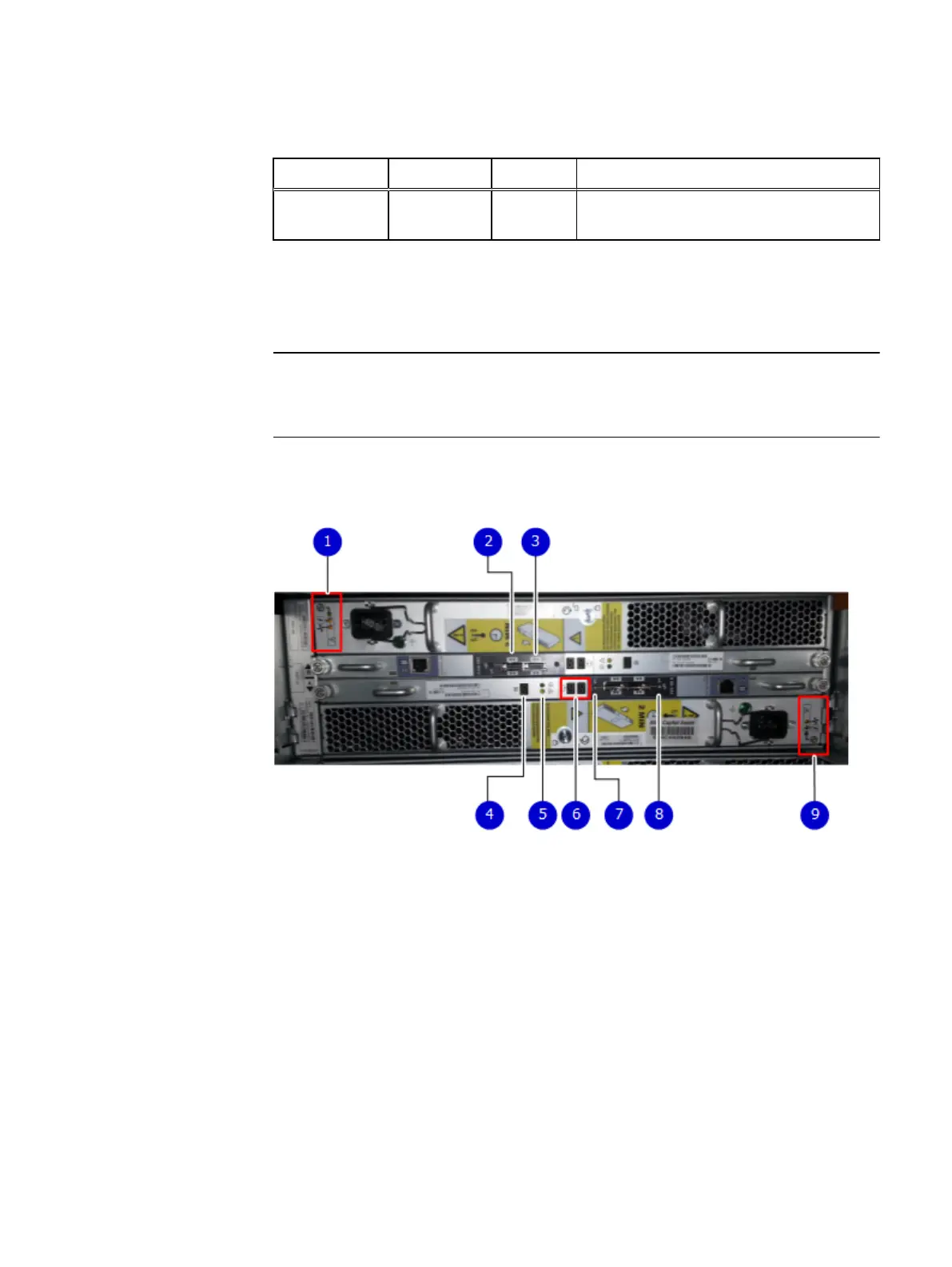
Figure 3 Back panel: Power modules and controllers
1. LEDs
l
Power supply B: Power LED
l
Power fault: Amber
l
Blower fault: Amber
2. Expansion (Out)
3. Host (In)
4. Enclosure address (not used)
5. Power (Green) or Fault (Amber)
6. Bus ID (not used)
7. Host link active
8. Expansion link active
9. LEDs
Shelf Installation Overview
Back panel: Power/cooling module and shelf controllers 13
 Loading...