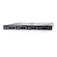
Figure 48. Cabling diagram—systems with the 2.5 inch (x4 sas and x2 pcie ssd) hard-drive backplane
1
cable retention bracket 2 system board
3 PCIe SSD card 4 integrated SAS controller card
5 SAS connector on system board 6 SAS and PCIe SSD backplane
Figure 49. Removing and installing the 2.5 inch (x8) hard-drive backplane
1
backplane signal cable 2 backplane power cable
3 SAS A cable 4 release tabs (2)
Installing and removing system components 83
 Loading...

