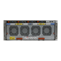
Table 5 Rear LED status indicators (continued)
Part Description or Location State
Power supply DC LED Steady green indicates normal
DC output power.
Power supply Service LED Solid amber indicates a failed
power supply.
I/O module I/O module handle Solid green, I/O module
functioning normally; amber
indicates a fault condition.
Each IO module also has per
port LEDs. These are blue on
the FC, and SAS I/O modules.
They light when the port is
active.
Management module Bicolor LED Solid green, management
module functioning normally;
amber indicates the
management module requires
service.
Available I/O modules
I/O modules may include:
l
Quad port Ethernet 10GBase-SR Optical with LC connectors
l
Quad port Ethernet 10GBase-CX1 Direct Attach Copper with SPF+ module
l
Quad port Ethernet 10GBase-T Copper
l
Dual port 16 Gbps Fibre Channel
l
Quad port 6 Gbps SAS
I/O module port physical mapping
I/O module ports are numbered starting with 0. When the I/O modules are inserted
vertically into the system chassis, port 0 is on the bottom.
I/O module port logical mapping
The numerical port labels on the I/O modules are identified logically in the DD OS
software by the following descriptions:
l
I/O module type
l
I/O module slot
l
Alphabetic character corresponding to the physical port number
The following example is based on a four-port Ethernet I/O module installed in slot 1 of
the system chassis.
Table 6
Physical to logical port mapping example
Physical port Logical identifier
0 eth1a
Hardware Overview
26 Data Domain DD9500 and DD9800 Systems 6.1 Hardware Overview and Installation Guide
 Loading...

