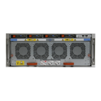
Figure 17 Open fan tray
Do not loosen the blue thumbscrew on the SP latch handle to access the fan tray. Use
the orange thumbscrews on the front as shown in the picture.
1. Left fan tray thumbscrew
2. Front panel left handle
3. Front panel right handle
4. Right fan tray thumbscrew
5. Location map of the fans
DIMM Modules
DD9500/DD9800 systems contain the following memory configurations:
Table 9
DD9500/DD9800 memory configurations
System Base Expanded ER/DD Cloud Tier
DD9500 32 x 8 GB DIMMs
(256 GB)
32 x 8 GB DIMMs + 16
x 16 GB DIMMs (512
GB)
32 x 8 GB DIMMs + 16
x 16 GB DIMMs (512
GB)
DD9800 32 x 8 GB DIMMs
(256 GB)
32 x 8 GB DIMMs
+ 32 x 16 GB DIMMS
(768 GB)
32 x 8 GB DIMMs
+ 32 x 16 GB DIMMS
(768 GB)
Cooling Fans
A system contains 8 hot-swappable cooling fans in a 7+1 redundant configuration,
located in the front of the system within a movable fan tray. The fans provide cooling
for the processors, DIMMs, and I/O modules. Each fan has an LED which glows amber
when the fan is failed or faulted. A system can run with one fan faulted.
Hardware Overview
32 Data Domain DD9500 and DD9800 Systems 6.1 Hardware Overview and Installation Guide