Warning about lifting the system.................................................................................13
Front panel components..............................................................................................18
Service LEDs...............................................................................................................19
Power button............................................................................................................. 20
Front LEDs................................................................................................................. 20
SSD drives.................................................................................................................. 21
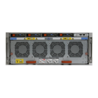
Features on rear of chassis.........................................................................................22
Serial number tag location.......................................................................................... 22
Four power supplies....................................................................................................23
Management module.................................................................................................. 24
1000BaseT Ethernet ports..........................................................................................24
Rear LEDs.................................................................................................................. 25
Power supply LEDs.....................................................................................................25
Location of NVRAM and I/O modules......................................................................... 27
SP module ..................................................................................................................31
Releasing a memory riser ........................................................................................... 31
Open fan tray............................................................................................................. 32
Warning about lifting the system................................................................................ 38
Rail bracket inside...................................................................................................... 39
Rail bracket outside.................................................................................................... 39
Cable management assembly (CMA)..........................................................................40
Insert screw in the back.............................................................................................. 41
Insert screw in the front............................................................................................. 42
Attach bracket to front of rack...................................................................................42
Adapters.....................................................................................................................43
Attaching the front rail with the screw....................................................................... 44
Attach front rail adapter ............................................................................................ 45
Warning about lifting the system................................................................................ 45
System on a rack ....................................................................................................... 46
Location of serial number tag......................................................................................47
Data Domain CMA back ............................................................................................. 48
Data Domain cable management assembly back inside............................................... 48
Rear of the rack mount rail ........................................................................................ 49
Node 0 SAS I/O module to ES30 host port connector............................................... 53
Node 1 SAS I/O module to ES30 expansion port connector........................................54
Cables for ES30 to ES30 connections........................................................................55
Cabling for base DD9500 /DD9800 systems.............................................................. 58
Cabling for HA DD9500 /DD9800 systems in one rack...............................................60
Cabling for HA DD9500 /DD9800 systems in two racks.............................................63
Cabling for DD9500 /DD9800 systems with DD Cloud Tier (Single node or HA) .......66
Cabling for DD9500 /DD9800 systems with ERSO ................................................... 68
SAS I/O module to DS60 connector...........................................................................69
Cabling for base DD9500 and DD9800 systems..........................................................72
Cabling for HA DD9500 and DD9800systems............................................................. 74
Cabling for DD9500 and DD9800 systems with DD Cloud Tier................................... 76
Cabling for HA DD9500 and DD9800 systems with DD Cloud Tier..............................79
Cabling for DD9500 and DD9800 systems with ERSO................................................ 81
DD9500/DD9800 HA interconnect.............................................................................82
Power LED and power button..................................................................................... 87
1
2
3
4
5
6
7
8
9
10
11
12
13
14
15
16
17
18
19
20
21
22
23
24
25
26
27
28
29
30
31
32
33
34
35
36
37
38
39
40
41
42
43
44
45
46
47
48
49
FIGURES
Data Domain DD9500 and DD9800 Systems 6.1 Hardware Overview and Installation Guide 5