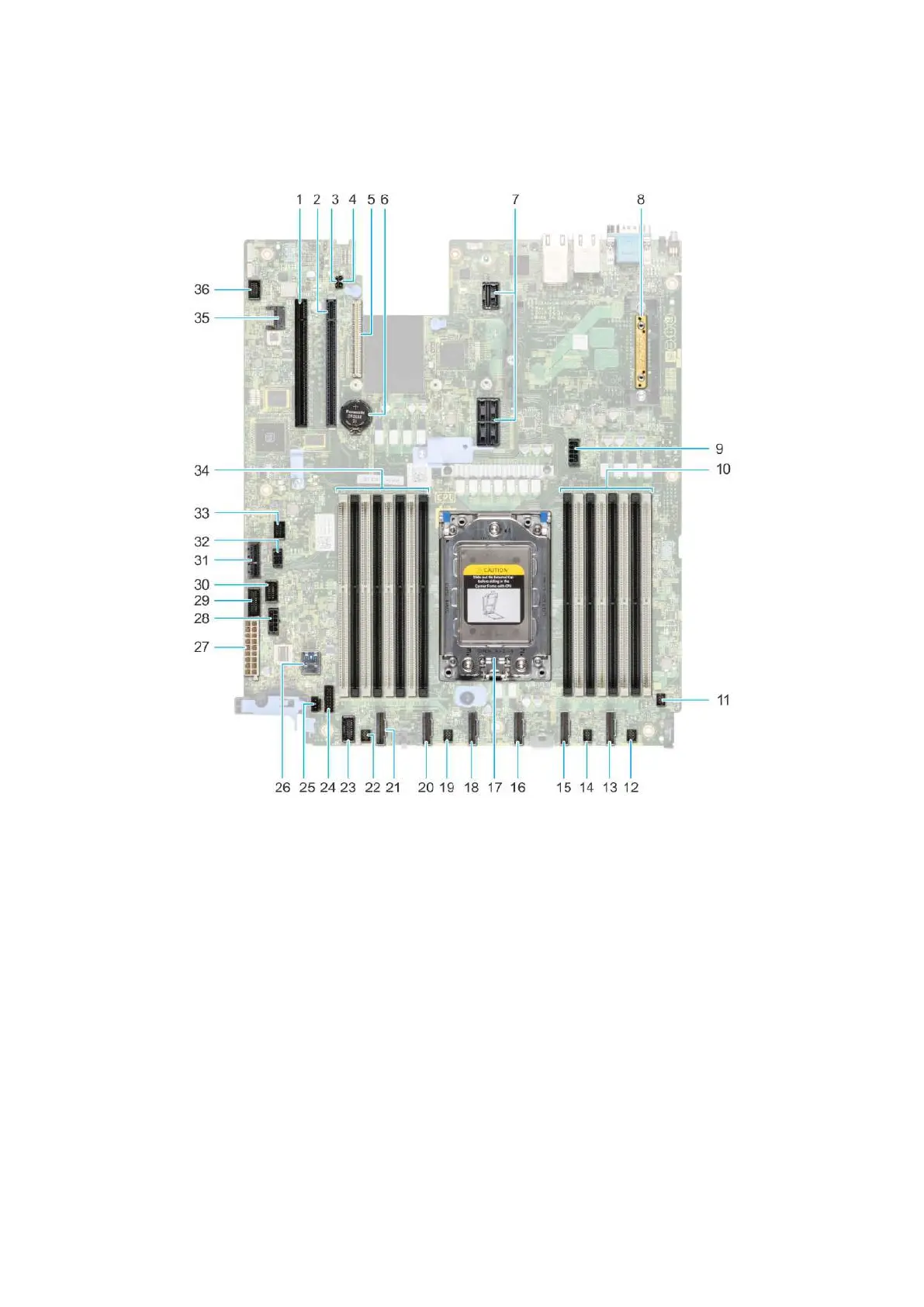
System board connectors
Figure 131. System board connectors
1.
PCI card Slot 5 2. PCI card Slot 4
3. PWRD_EN (Jumpers) 4. NVRAM_CLR (Jumpers)
5. LOM riser card 6. Battery
7. Riser slot 1A/Riser slot 1B 8. Mini PERC
9. System power 3 10. DIMMS for processor
11. Fan 6 12. Fan 5
13. SATA_A/PCIE_A 14. Fan 4
15. PCIE-B 16. SATA_B/PCIE_C
17. Processor 18. PCIE-D
19. Fan 3 20. PCIE-E
21. PCIE-F 22. Fan 2
23. Left control panel 24. Front backplane signal 1
25. Intrusion switch 26. Internal USB 3.0
27. System power 1 28. System power 2
29. PIB signal 2 30. PIB signal 1
31. IDSDM 32. Rear backplane/ ODD power
126 Jumpers and connectors

 Loading...