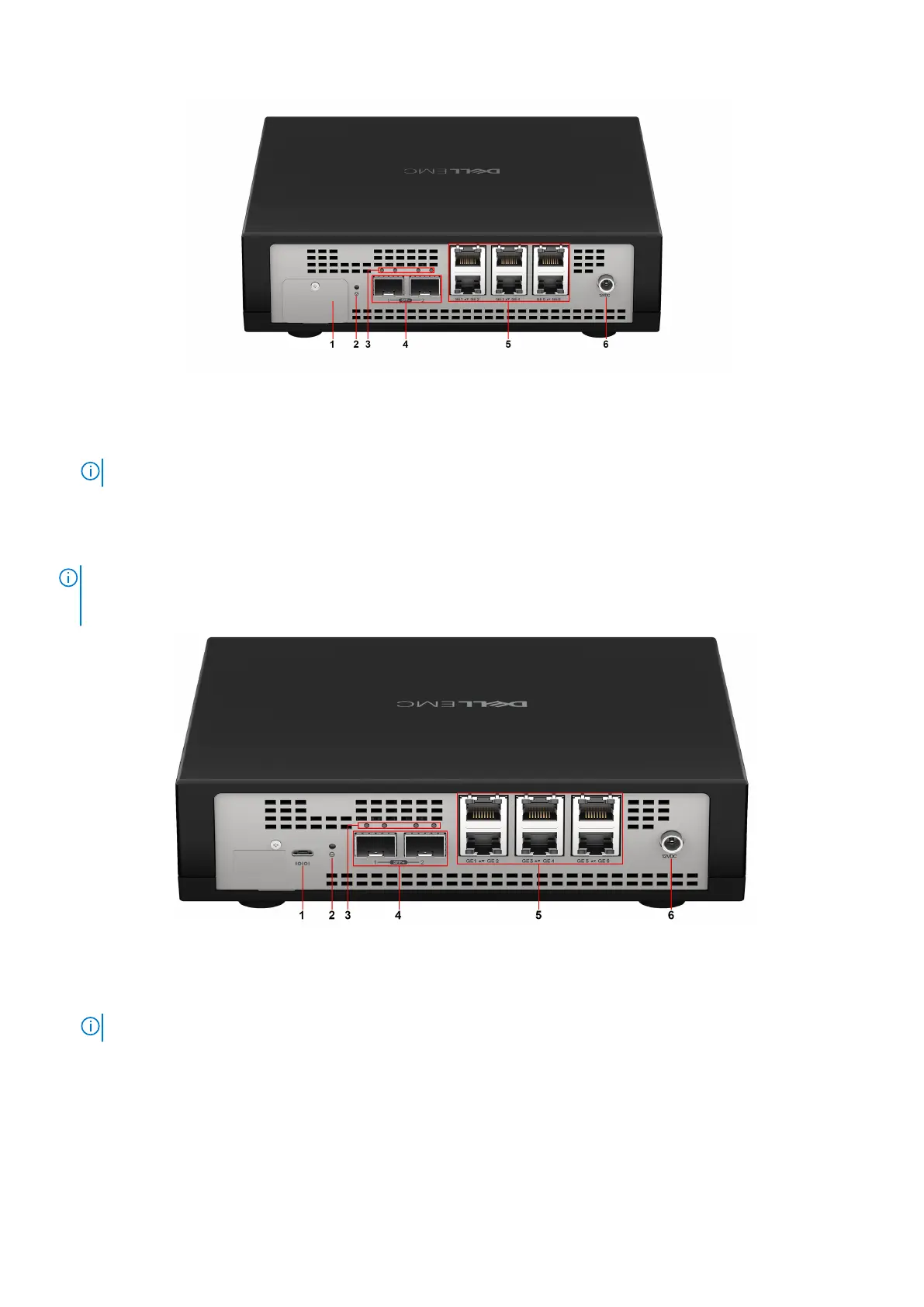
Figure 2. VEP1405 series rear view (with port cover)
1. Port cover
2. Reset button
NOTE: See the Reset button behavior table below for more information.
3. LED status indicators for SFP+ ports
4. SFP+ ports
5. Ethernet ports and LED status indicators
6. Power connection port
NOTE:
To prevent the VEP1405 series system console port from being accessed in a nonsecure location, the system
ships from the factory with a plate covering the micro USB port. To uncover the port, use a #0 (2.5 mm) Phillips head
screwdriver to loosen or remove the screw that holds the plate in place.
Figure 3. VEP1405 series back view (without port cover)
1. Micro USB serial console port
2. Reset button
NOTE: See the Reset button behavior table below for more information.
3. LED status indicators for SFP+ ports
4. SFP+ ports
5. Ethernet ports and LED status indicators
6. Power connection port
Introduction
7
 Loading...