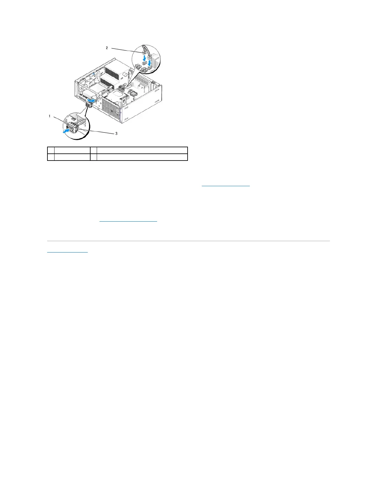
4. Push the I/O connector block into the I/O assembly opening until it snaps into place.
5. Plug the I/O assembly cable connectors into their system board connectors (see System Board Components).
6. Join the I/O assembly cables to the cable bundle routed through the middle of the chassis.
7. Replace the bezel.
8. Perform the procedure After Working on Your Computer).
9. Reboot your computer and exercise the I/O panel to ensure that it is working properly.
Back to Contents Page