About this task
NOTE: The heat-sink may become hot during normal operation. Allow sufficient time for the heat-sink to cool before you
touch it.
NOTE: For maximum cooling of the processor, do not touch the heat transfer areas on the heat-sink. The oils in your skin
can reduce the heat transfer capability of the thermal grease.
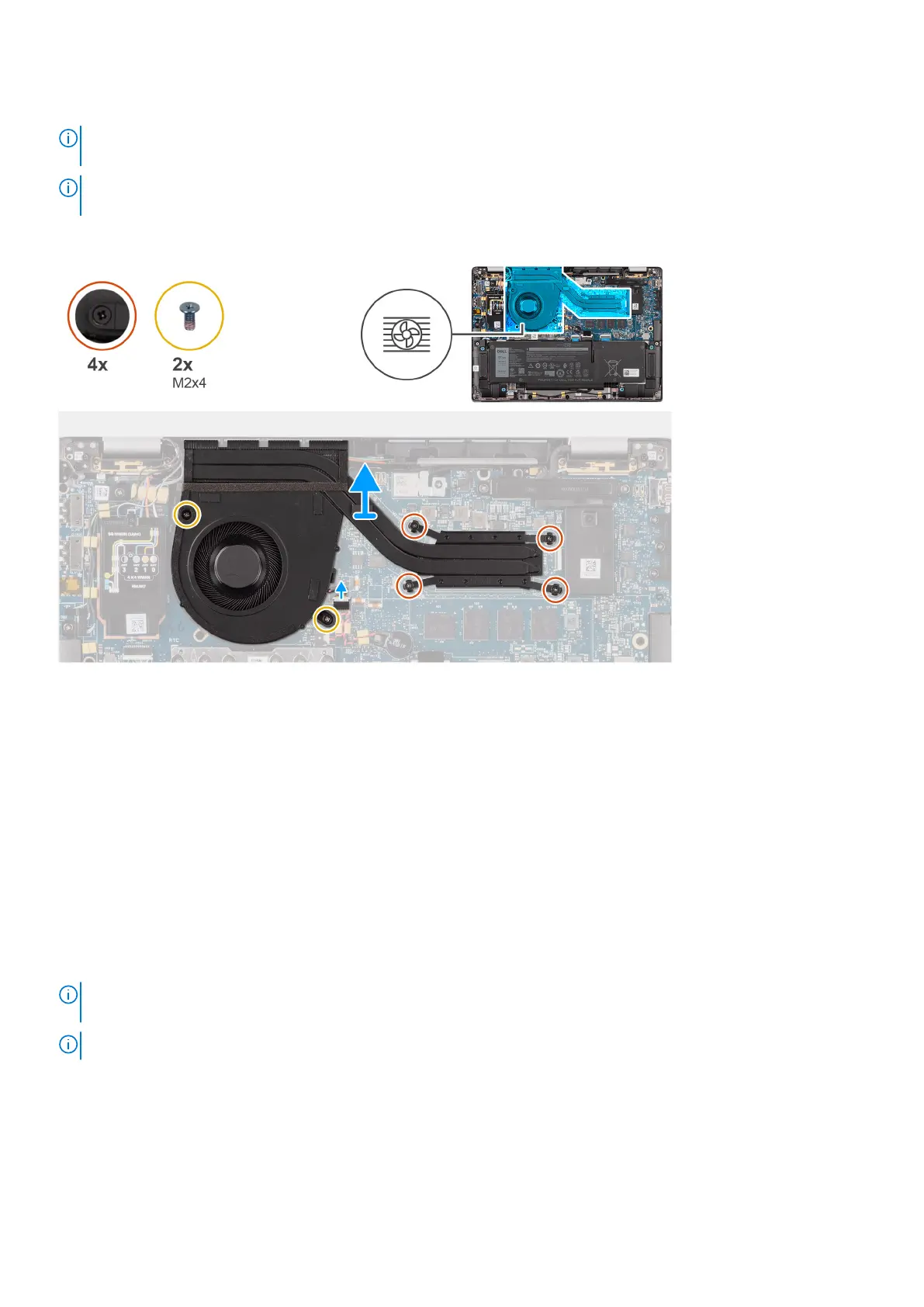
The following image indicates the location of the heat-sink and provides a visual representation of the removal procedure.
Steps
1. Disconnect the system fan cable from the connector on the system board.
2. Remove the four screws (M2x4) that secure the thermal fan to the system board.
3. In reverse sequential order (as indicated on the heat-sink), loosen the four captive screws that secure the heat-sink and fan
assembly to the system board.
4. Lift the heat-sink off the system board.
Installing the heat-sink and fan assembly
Prerequisites
If you are replacing a component, remove the existing component before performing the installation procedure.
About this task
NOTE:
If either the system board or the heat-sink is replaced, use the thermal grease provided in the kit to ensure that
thermal conductivity is achieved.
NOTE: Incorrect alignment of the heat-sink can damage the system board and processor.
The following image indicates the location of the heat-sink and provides a visual representation of the installation procedure.
Removing and installing components
31