NOTE: When replacing the system board, the CPU absorber sticker adhered onto the system board must be peeled off and
transferred over to the replacement system board.
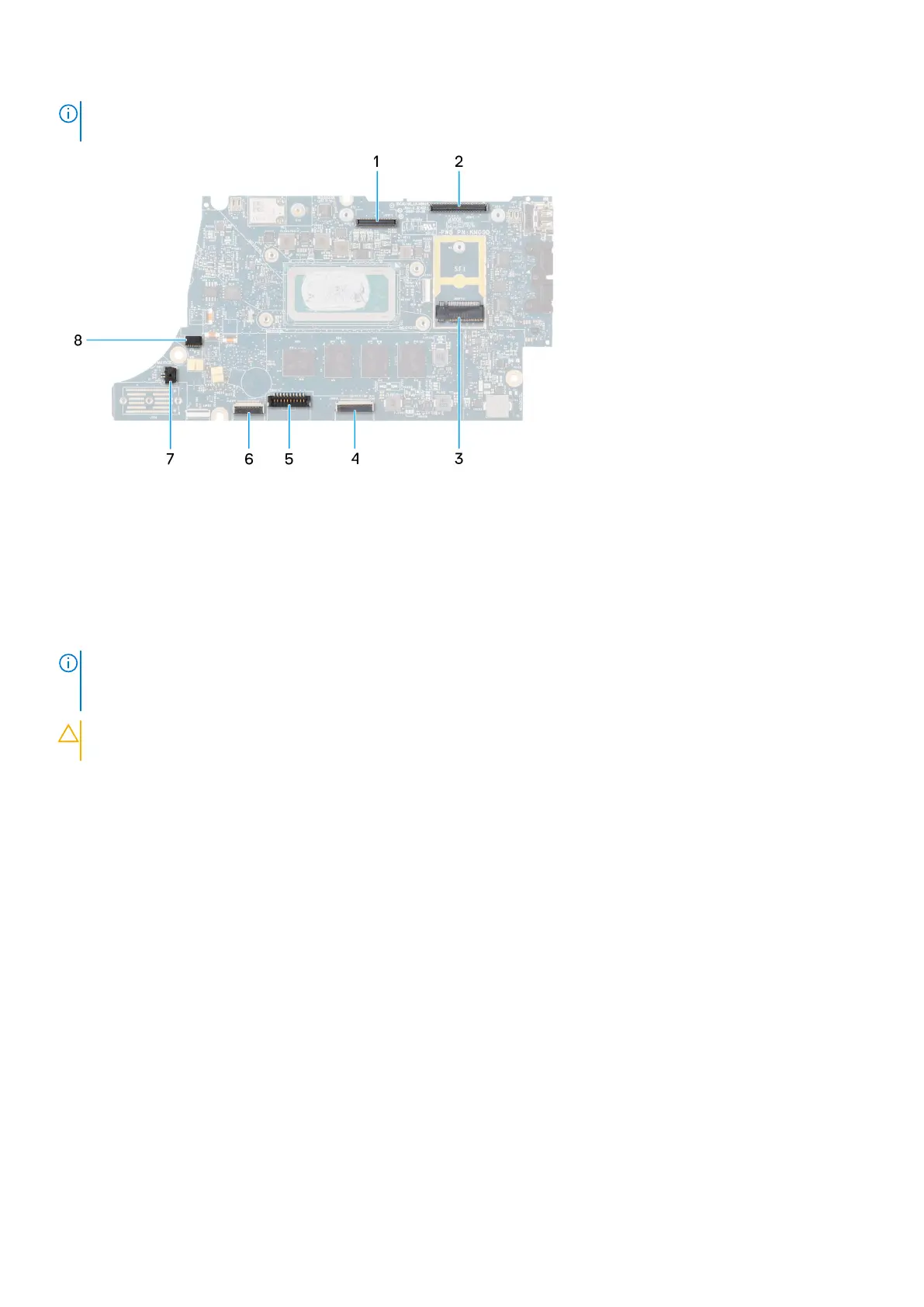
1. LCD connector
2. Touchscreen and IR-camera cable connector
3. M.2 solid-state drive connector
4. Clickpad FFC connector
5. Battery cable connector
6. USH daughter-board FFC connector
7. Coin-cell battery cable connector
8. Fan connector
NOTE:
For computers shipped without a WWAN card, a 4G/5G WWAN shielding cover and WWAN bracket (for 4G WWAN
card) is pre-installed to the computer. As a result, follow the steps in the WWAN card removal/installation section to
remove the WWAN shielding cover and WWAN bracket before removing the system board.
CAUTION: Install the heat-sink after installing the system board as there are two screws (M2x3) underneath the
heat-sink, that secure the system board to the computer, that need to be installed first.
The following images indicate the location of the system board and provide a visual representation of the installation procedure.
50
Removing and installing components