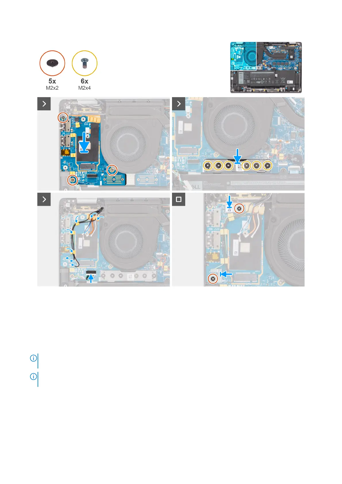
Figure 75. Installing the I/O daughterboard
Steps
1. Adhere the WWAN thermal pad that is affixed to the WWAN card compartment and move it to the new I/O daughterboard if
you are replacing the I/O daughterboard for models that are shipped with 5G WWAN card.
2. Place the I/O daughterboard in its compartment from the gap in its top side and place it on the computer.
3. Replace the three screws (M2x2.5) securing the I/O daughterboard to palm-rest and keyboard assembly.
4. Replace the bridge connector board from the computer.
NOTE:
Orient the I/O daughterboard bridge connection board so that the arrows etched on the connector point upward
towards the heat-sink and fan assembly when re-installing it.
NOTE: When re-installing the I/O daughterboard bridge connector board secure the six screws (M2x4) in sequential
order (1 > 2 > 3 > 4 > 5 > 6) marked on the FPC.
5. Replace the six screws (M2x4) that secures the I/O daughterboard bridge connector board to palm-rest and keyboard
assembly.
6. Connect the speaker cable from the I/O daughterboard.
7. Connect the fingerprint reader FPC from the I/O daughterboard.
8. Align and place the fingerprint reader bracket to the computer.
9. Replace the fingerprint reader bracket from the computer for the models shipped with a fingerprint reader.
Removing and installing Field Replaceable Units (FRUs)
103