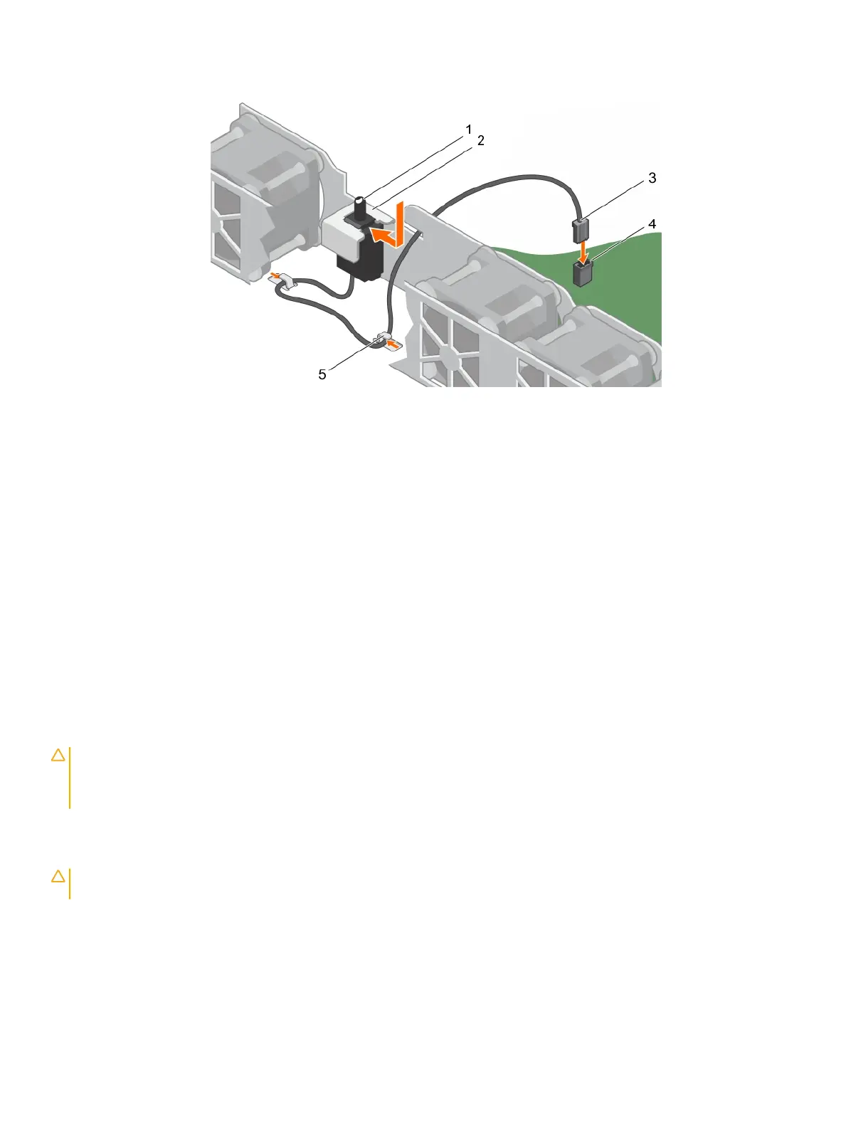
Figure 20. Installing the intrusion switch
1 intrusion switch 2 intrusion switch slot
3 intrusion switch cable 4 intrusion switch connector on the system board
5 cable routing clip (2)
Next step
Follow the procedure listed in After working inside your system.
Cooling shroud
The cooling shroud aerodynamically directs the airow across the entire system. The airow passes through all the critical parts of the
system, where the vacuum pulls air across the entire surface area of the heat sink, thus allowing increased cooling.
Removing the cooling shroud
Prerequisites
CAUTION
: Many repairs may only be done by a certied service technician. You should only perform troubleshooting and simple
repairs as authorized in your product documentation, or as directed by the online or telephone service and support team.
Damage due to servicing that is not authorized by Dell is not covered by your warranty. Read and follow the safety instructions
that are shipped with your product.
1 Ensure that you follow the Safety instructions.
2 Follow the procedure listed in Before working inside your system.
CAUTION
: Never operate your system with the air shroud removed. The system may get overheated quickly, resulting in
shutdown of the system and loss of data.
Step
Hold the cooling shroud and lift it away from the system.
60
Installing and removing system components
 Loading...