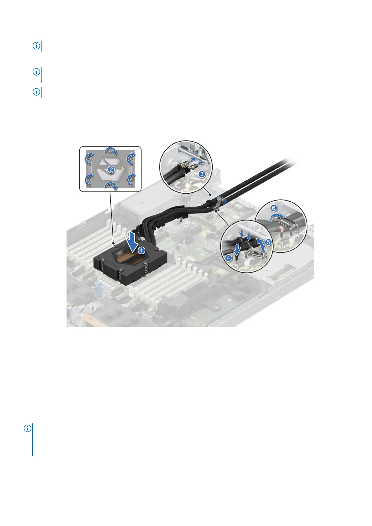
NOTE: Follow the screw sequence defined on heat sink label. Assembly order: 1, 2, 3, 4, 5, 6.
3. Route the DLC tubes to the rear of the system through the RIO board.
NOTE: Leak detection cable must be placed first into the clip (underneath the cooling tubes), and then place tube 2 and
tube 1 into the clip to ensure that cable does not interfere with the PCIe risers.
NOTE: Follow the number labels on the DLC tubes and ring holders (1,2).
4. Connect the DLC leak detection cable to the connector on RIO.
5. Align the rubber ring on the tubes with the ring holder.
6. Tilt the DLC ring holder and using a Phillips #2 screwdriver, tighten the captive screw on the DLC ring holder to secure it in
place.
Figure 77. Installing the DLC module
Next steps
1. Install the expansion card riser.
2. Install the air shroud.
3. Follow the procedure listed in the After working inside your system.
Expansion cards and expansion card risers
NOTE:
A system event entry is logged in the iDRAC Lifecycle Controller if an expansion card riser is not supported or
missing. It does not prevent your system from turning on. However, if a F1/F2 pause occurs with an error message,
see Troubleshooting expansion cards section in the Dell EMC PowerEdge Servers Troubleshooting Guide at www.dell.com/
poweredgemanuals.
110 Installing and removing system components
 Loading...


