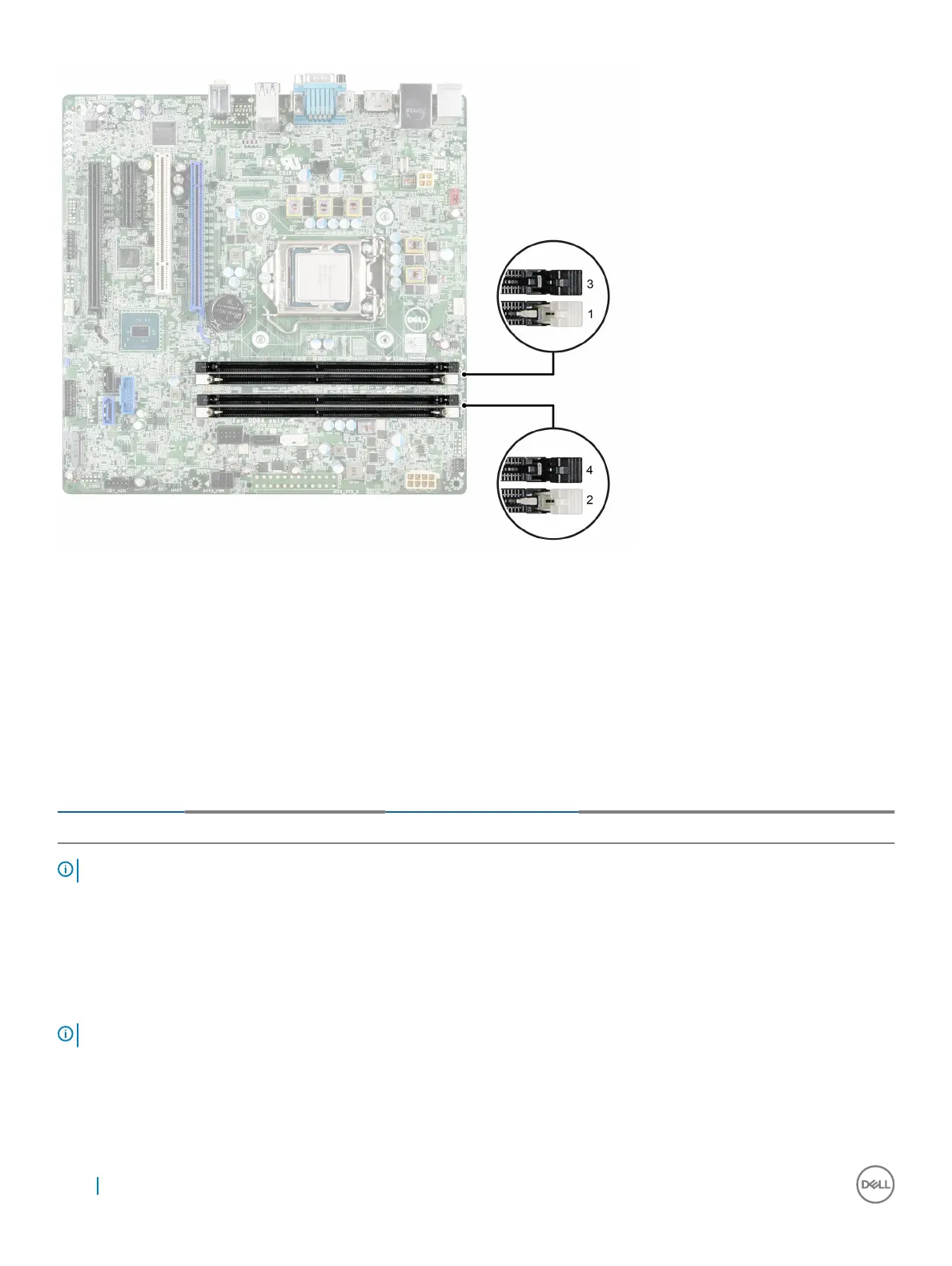
Figure 34. Memory socket locations on the system board
Memory channels are organized as follows:
• Channel 0: memory sockets 1 and 3
• Channel 1: memory sockets 2 and 4
The following table shows the memory population and operating frequencies for the supported configurations.
Table 35. Supported memory
Memory module
type
Memory modules populated
per channel
Operating frequency (in
MT/s)
Maximum memory module
rank per channel
Operating
voltage
UDIMM
Two
2133, 2400
Four 1.2 V
NOTE: MT/s indicates DIMM speed in MegaTransfers per second.
General memory module installation guidelines
Memory configurations that fail to observe these guidelines can prevent your system from booting, stop responding during memory
configuration, or operating with reduced memory.
NOTE
: This system supports only UDIMMs.
The system supports Flexible Memory Configuration, enabling the system to be configured and run in any valid chipset architectural
configuration. The following are the recommended guidelines for installing memory modules:
• Up to two UDIMMs can be populated in a channel.
70
Installing and removing system components