112 Installing System Components
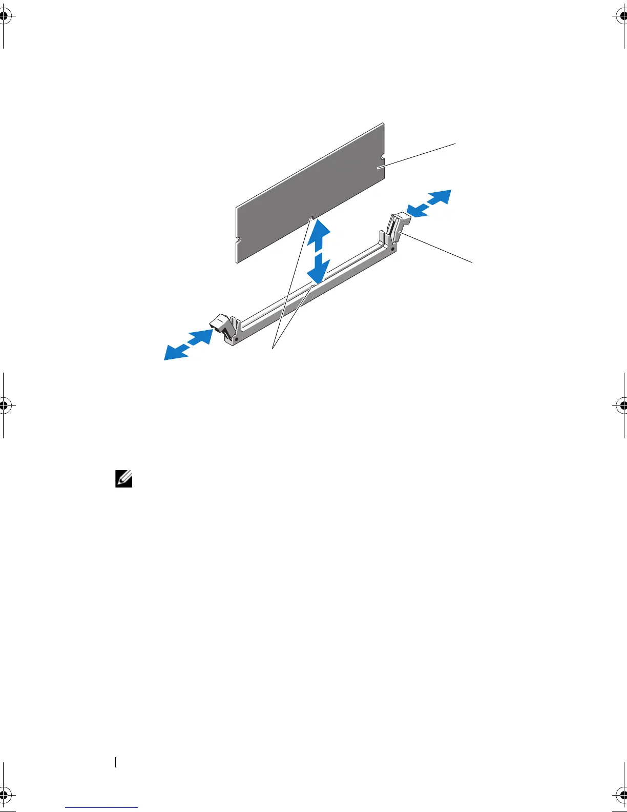
Figure 3-17. Installing and Removing a Memory Module
10
Align the memory module's edge connector with the alignment key of the
memory module socket, and insert the memory module in the socket.
NOTE: The memory module socket has an alignment key that allows you
to install the memory module in the socket in only one way.
11
Press down on the memory module with your thumbs to lock the memory
module into the socket.
When the memory module is properly seated in the socket, the ejectors on
the memory module socket align with the ejectors on the other sockets
that have memory modules installed.
12
Repeat step 8 through step 11 of this procedure to install the remaining
memory modules. See Table 3-1 and Table 3-2.
13
Replace the cooling shroud. See "Installing the Cooling Shroud" on
page 89.
14
Replace the expansion card stabilizer. See "Installing the Expansion Card
Stabilizer" on page 87.
15
Close the system. See "Closing the System" on page 86.
1 memory module 2 memory module socket ejectors (2)
3 alignment key
book.book Page 112 Wednesday, August 19, 2009 4:40 PM