EasyManua.ls Logo

Dell PowerEdge T360 - User Manual

Dell PowerEdge T360
144 pages
Print Icon
To Next Page IconTo Next Page
Loading...
Dell PowerEdge T360
Installation and Service Manual
Regulatory Model: E78S
Regulatory Type: E78S002
March 2024
Rev. A01

Table of Contents

Question and Answer IconNeed help?

Do you have a question about the Dell PowerEdge T360 and is the answer not in the manual?

Overview

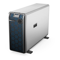
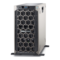
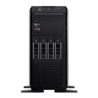
The Dell PowerEdge T360 is a single-socket 4.5U tower server designed for various enterprise applications. It supports one Intel Xeon E-2400 series processor with up to eight cores or an Intel Pentium G7400/G7400T processor with up to two cores. The system features four UDIMM slots for memory, a cabled AC or two redundant AC or DC power supply units, and flexible storage options including up to 8 x 3.5-inch SAS/SATA HDD/SSD drives, up to 4 x 3.5-inch SATA HDD/SSD drives, or up to 8 x 2.5-inch SAS/SATA HDD/SSD drives with 3.5-inch to 2.5-inch adapters. All SAS and SATA drives are referred to as "drives" unless specified otherwise.

Important Technical Specifications:

  • Chassis Dimensions:
    • 8 x 3.5-inch SAS/SATA HDD/SSD configuration: Xa (width) 175.0 mm (6.89 inches), Ya (height) 369.5 mm (14.55 inches), Yb (height with bezel) 382.5 mm (15.06 inches), Za (depth with bezel) 19 mm (0.75 inches), Zc (total depth) 562.12 mm (22.13 inches).
  • System Weight:
    • With fully populated drives: 25.10 kg (55.34 lbs)
    • Without drives and PSU installed: 18.29 kg (40.32 lbs)
  • Processor: Intel Xeon E-2400 series or Intel Pentium G7400/G7400T, supporting one processor.
  • PSU Specifications:
    • 450 W Platinum: 100–120 V (450 W), 200–240 V (450 W), 6.5 A - 3.5 A current.
    • 600 W Mixed Mode Platinum: 100–120 V (600 W), 200–240 V (600 W), 7.1 A - 3.6 A current.
    • 700 W Mixed Mode Titanium: 200–240 V (700 W), 4.1 A current.
    • Supports IT power systems with phase-to-phase voltage not exceeding 240 V.
    • PSU power cords: Cabled PSU 106 mm (450 W AC, C13/C14), Redundant 60 mm (600 W AC, C13/C14), 700 W AC (C13/C14).
  • Cooling Fan: Supports one standard (STD) or High Performance (HPR) cooling fan.
  • Supported Operating Systems: Canonical Ubuntu Server LTS, Microsoft Windows Server with Hyper-V, Red Hat Enterprise Linux, SUSE Linux Enterprise Server, VMware ESXi.
  • System Battery: One CR 2032 3.0-V lithium coin cell battery.
  • Expansion Card Riser: Four PCIe slots (three Gen4 and one Gen5) on the system board.
    • Slot 1 (Gen4): Full Height, Half Length, x4.
    • Slot 2 (Gen5): Full Height, Half Length, x16.
    • Slot 3 (Gen4): Full Height, Half Length, x1.
    • Slot 4 (Gen4): Full Height, Half Length, x4.
  • Memory: DDR5 UDIMM ECC memory.
    • Single rank: 16 GB (min 16 GB, max 64 GB per processor).
    • Dual rank: 32 GB (min 32 GB, max 128 GB per processor).
    • 4, 288-pin sockets, up to 4400 MT/s. Memory DIMM slots are not hot pluggable.
  • Storage Controller Cards: Internal (PERC H355 Adapter, PERC H755 Adapter, HBA355i Adapter), Internal Boot (BOSS-N1 with HWRAID 2 x M.2 NVMe SSDs), Software RAID (S160), External (HBA355e Adapter).
  • Drives: Up to 4 x 3.5-inch SATA HDD/SSD, up to 8 x 3.5-inch SAS/SATA HDD/SSD, up to 8 x 2.5-inch SAS/SATA HDD/SSD with 3.5-inch to 2.5-inch adapter.
  • Optical Drives: One Slim SATA DVD-ROM drive or DVD +/- RW drive (data only).
  • GPU: One 60 W single-width GPU. Systems with GPUs have higher fan acoustics.
  • Ports and Connectors:
    • Front: USB 3.2 port (1), iDRAC Direct (Micro-AB USB) port (1), Optical drive bay, Drive Bay, BOSS-N1 (optional).
    • Rear: Power supply units (PSU 1, PSU 2), PCIe expansion card slots (4), USB 2.0 (2), USB 3.2 (2), System Identification (ID) button, NIC port (2), Dedicated iDRAC Ethernet port, VGA port, Serial port.
  • Video: Integrated Matrox G200eW graphics controller with 16 MB frame buffer. Supports various resolutions from 640x480 to 1920x1200 at 60-85 Hz with 32-bit color depth.
  • Environmental Specifications (Continuous Operation):
    • ASHRAE A2: 10–35°C (50–95°F) up to 900 m, 8-80% RH. Max temp reduced by 1°C/300 m above 900 m.
    • ASHRAE A3: 5–40°C (41–104°F) up to 900 m, 8-85% RH. Max temp reduced by 1°C/175 m above 900 m.
    • ASHRAE A4: 5–45°C (41–113°F) up to 900 m, 8-90% RH. Max temp reduced by 1°C/125 m above 900 m.
    • Rugged Environment: 5–55°C (41–131°F) up to 900 m, 8-90% RH. Max temp reduced by 1°C/125 m above 900 m.
    • Maximum temperature gradient: 20°C/hour (operation/non-operation), 5°C/15 minutes (tape), 5°C/hour (tape).
    • Non-operational temperature limits: -40 to 65°C (-40 to 149°F).
    • Non-operational humidity limits: 5% to 95% RH with 27°C (80.6°F) maximum dew point.
    • Maximum non-operational altitude: 12,000 meters (39,370 ft).
    • Maximum operational altitude: 3,048 meters (10,000 ft).
  • Maximum Vibration: Operating 0.26 Grms (5-350 Hz), Storage 1.88 Grms (10-500 Hz for 15 minutes, all six sides tested).
  • Maximum Shock Pulse: Operating 6 G (up to 11 ms, 6 pulses), Storage 71 G (up to 2 ms, 6 pulses).
  • Thermal Restriction Matrix: Specifies HSK/FAN types (HPR/STD, STD/STD) based on CPU TDP and number of cores for 4x3.5-inch SATA and 8x3.5-inch SAS/SATA configurations. HPR PCI fan and PCIe shroud are needed if BOSS, A2 GPU, or a PCIe card >25 W and Broadcom 10 G NIC is installed.

Usage Features:

  • Initial Setup and Configuration: Guides users through unpacking, connecting peripherals, and powering on the system.
  • iDRAC Configuration: Provides options to set up iDRAC IP address (DHCP by default, static IP available on request) and log in to the iDRAC Web User Interface using iDRAC user, Microsoft Active Directory user, or LDAP user credentials. The iDRAC Direct port (Micro-AB USB) allows direct access.
  • Operating System Installation: Resources and documentation links are provided for installing supported operating systems, including using iDRAC, Lifecycle Controller, OpenManage Deployment Toolkit, and Dell certified VMware ESXi. Dell recommends using Lifecycle Controller for OS installation as it installs all required drivers.
  • Driver and Firmware Downloads: Instructions for downloading the latest BIOS, drivers, and system management firmware from the Dell support site using various methods like iDRAC with LC, Dell Repository Manager, Server Update Utility, OpenManage Deployment Toolkit, and iDRAC virtual media.
  • Pre-operating System Management Applications: Allows management of basic settings and features without booting to the operating system, including System Setup, Dell Lifecycle Controller, Boot Manager, and Preboot Execution Environment (PXE).
  • System Setup: Configures BIOS, iDRAC, and device settings. Accessible via F2 during boot.
    • System BIOS: Configures BIOS settings, including System Information, Memory Settings, Processor Settings, SATA Settings, Boot Settings, Network Settings, Integrated Devices, Serial Communication, System Profile Settings, System Security, Redundant OS Control, and Miscellaneous Settings.
    • Boot Settings: Allows setting boot mode (UEFI or BIOS), boot order, and enabling/disabling boot devices. UEFI is the default and supports drives larger than 2 TB, enhanced security, and faster boot times.
    • Network Settings: Configures UEFI PXE and HTTP device settings, including VLAN, IP address, subnet mask, and TLS authentication.
    • Integrated Devices: Configures USB ports (User Accessible, Internal, iDRAC Direct), Embedded NICs, I/OAT DMA Engine, Embedded Video Controller, OS Watchdog Timer, Empty Slot Unhide, and Slot Disablement.
    • Serial Communication: Configures serial communication options, port addresses, failsafe baud rate, remote terminal type, and redirection after boot.
    • System Profile Settings: Sets system profile (Performance Per Watt (OS), Performance, Custom), CPU Power Management, Memory Frequency, Turbo Boost, C1E, C-States, Memory Refresh Rate, Uncore Frequency, Dynamic Load Line Switch, Monitor/Mwait, PCI ASPM L1 Link Power Management, and Workload Configuration.
    • System Security: Configures CPU AES-NI, Strong Password Status, System Password, Setup Password, Password Status, and TPM Information (including TPM Security, Firmware, Hierarchy, and Advanced Settings).
  • Boot Manager: Selects boot options and diagnostic utilities (F11 during boot).
  • PXE Boot: Configures networked systems remotely (F12 during POST).
  • System Diagnostics: Runs diagnostics to test hardware without additional equipment or risking data loss. Accessible via F11 (Boot Manager) or F10 (Lifecycle Controller).

Maintenance Features:

  • Safety Instructions: Emphasizes performing repairs only by certified service technicians or as authorized by documentation/support, and using antistatic measures.
  • Component Installation and Removal: Detailed procedures for removing and installing various system components:
    • Front bezel
    • System feet
    • System cover
    • Air shroud (PCIe and standard)
    • Intrusion switch
    • Drive blanks, drive carriers, drives (2.5-inch and 3.5-inch), and 3.5-inch drive adapters
    • Optical drive blanks and optical drives
    • Drive backplane
    • Cooling fans (standard and HPR PCI fan)
    • System memory modules (with guidelines for optimal population)
    • Processor and heat sink (including thermal grease application)
    • Expansion cards and risers (with slot priority guidelines)
    • Optional BOSS-N1 module and card carrier
    • Power supply units (hot-swappable and cabled, including hot spare feature configuration)
    • Power interposer board
    • System battery
    • System board (including Easy Restore and manual Service Tag update)
    • Trusted Platform Module (TPM) (including upgrading and initializing for users)
    • Control panel assembly
  • Cable Routing: Diagrams and descriptions for connecting various cables within the system, including drive, power, and control panel cables.
  • Error Messages: Provides descriptions and recommended actions for configuration validation errors (e.g., HWC8010, HWC8011) and indicator codes (System Health, iDRAC Direct LED, NIC, PSU, Drive).
  • Getting Help: Provides resources for recycling/end-of-life information, contacting Dell Technologies support, accessing system information via Quick Resource Locator (QRL), and receiving automated support with Secure Connect Gateway (SCG).

Dell PowerEdge T360 Specifications

General IconGeneral
BrandDell
ModelPowerEdge T360
CategoryServer
LanguageEnglish

Related product manuals