9. Remove the heat sink (discrete GPU) or heat sink (integrated GPU), as applicable.
10. Remove the battery.
11. Remove the assembly-inner frame.
About this task
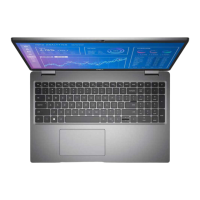
The following images indicate the system board connectors.
1. WWAN-card connector 2. WLAN-card connector
3. Sensor board-cable connector 4. Memory modules
5. Display-cable connector 6. System-fan connector
7. Solid-state drive Slot 1 8. Touchpad-cable connector
9. Battery-cable connector 10. Solid-state drive Slot 2
11. USH-cable connector 12. Coin-cell battery cable connector
13. Speaker-cable connector
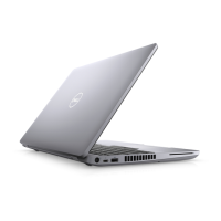
The following images indicate the location of the system board and provide a visual representation of the removal procedure.
Removing and installing Field Replaceable Units (FRUs)
85