Processor Module: Dell Precision M6400 Service Manual
file:///T|/htdocs/systems/wsm6400/en/sm/cpu.htm[11/16/2012 10:27:18 AM]
When the processor module is properly seated, all four corners are aligned at the same height. If one or more corners
of the module are higher than the others, the module is not seated properly.
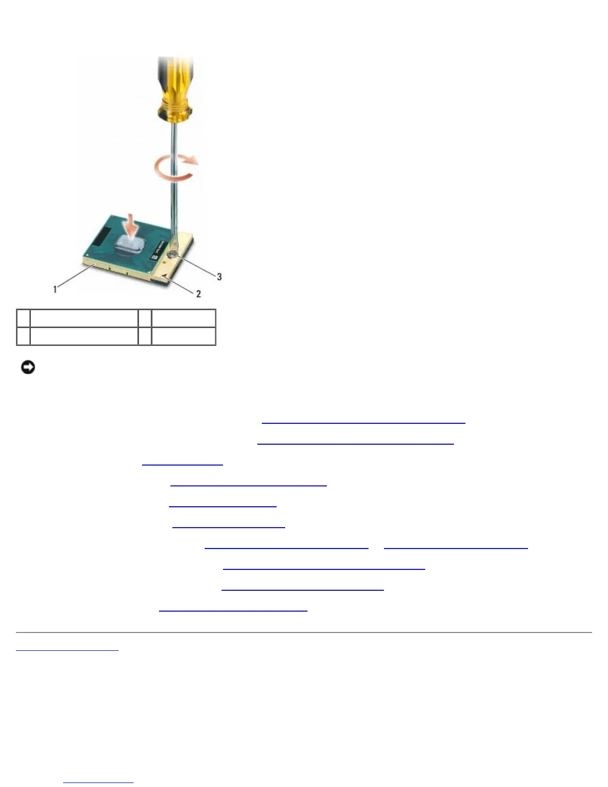
1 ZIF socket 2 pin-1 corner
3 ZIF-socket cam screw
NOTICE: To avoid damage to the processor, hold the screwdriver so that it is perpendicular to the
processor when turning the cam screw.
2. Tighten the ZIF socket by turning the cam screw clockwise to secure the processor module to the system board.
3. Replace the video card/heatsink assembly (see Replacing the Video Card/Heatsink Assembly
).
4. Replace the processor heatsink assembly (see Replacing the Processor Heatsink Assembly
).
5. Replace the fan (see Replacing the Fan
).
6. Replace the palm rest (see Replacing the Palm Rest Assembly
).
7. Replace the keyboard (see Replacing the Keyboard
).
8. Replace the LED cover (see Replacing the LED Cover
).
9. Replace the display assembly (see Replacing the Edge-to-Edge Display
or Replacing the Display Assembly).
10. Replace the secondary hard drive (see Replacing the Secondary Hard Drive (HDD2)
).
11. Replace the base assembly cover (see Replacing the Base Assembly Cover
).
12. Follow the procedures in After Working on Your Computer
.
Back to Contents Page