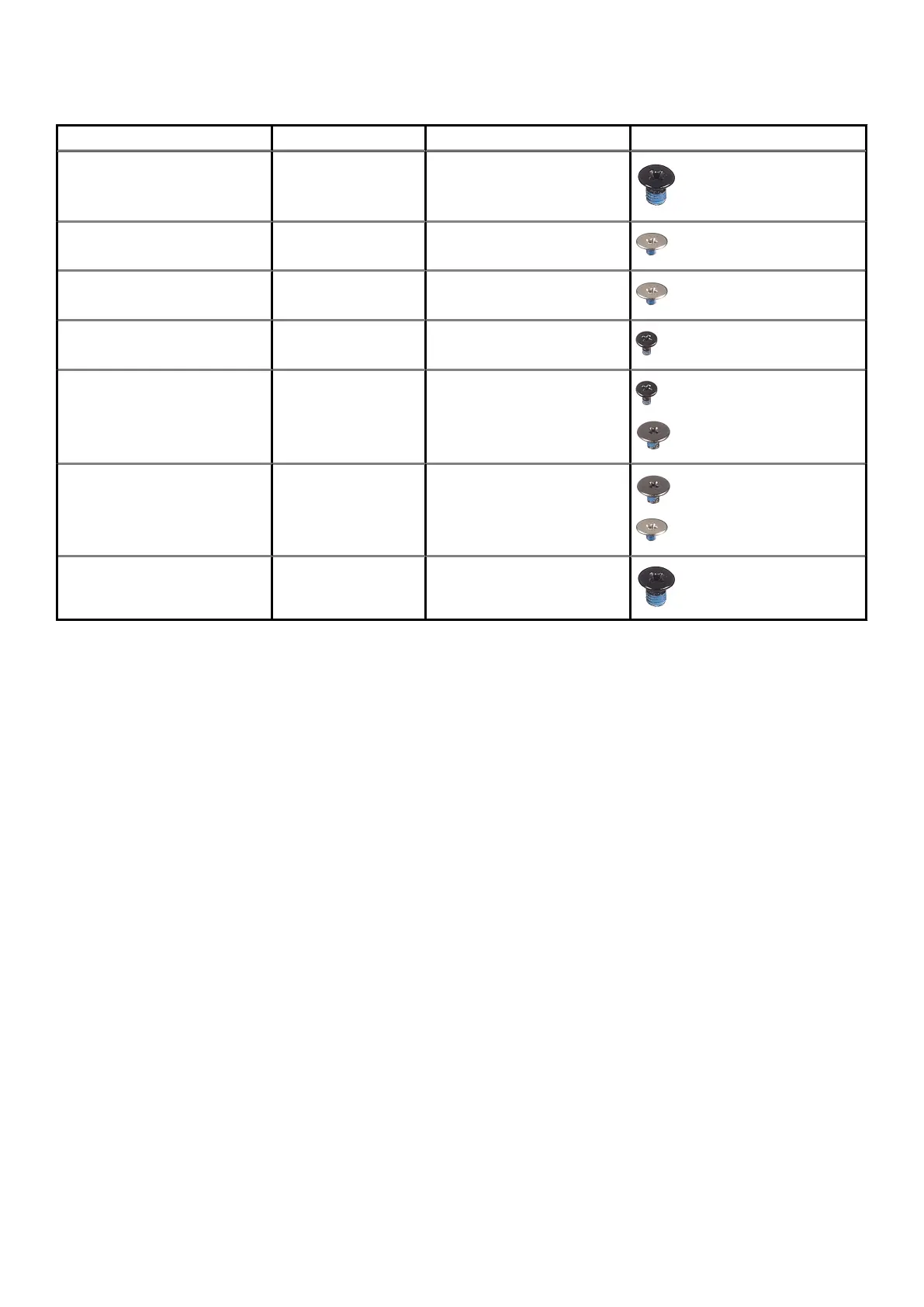
Table 1. Screw list(continued)
Component Screw type Quantity Screw image
Hinge screws
M2.5x3.5 6
I/O board
M2x2 4
System board
M2x2 2
DC-in port
M2x3 1
Power button with fingerprint
reader
M2x3
M1.6x2
1
1
Touchpad
M1.6x2
M2x2
3
2
Display assembly
M2.5x3.5 6
Base cover
Removing the base cover
Prerequisites
Follow the procedure in before working inside your computer.
About this task
The figure indicates the location of the base cover and provides a visual representation of the removal procedure.
Disassembly and reassembly
13