Table 1. Screw list (continued)
Component Secured to Screw type Quantity Screw image
Antenna modules Base panel M2x2.5 2
System board Display-assembly base M3 0.5x5 5
Base panel Display-assembly base M3x5 19
Display panel Display-assembly base M3 0.5x5 11
Media-card reader Display-assembly base M2x3 1
Back cover
Removing the back cover
Prerequisites
1. Follow the procedure in Before working inside your computer.
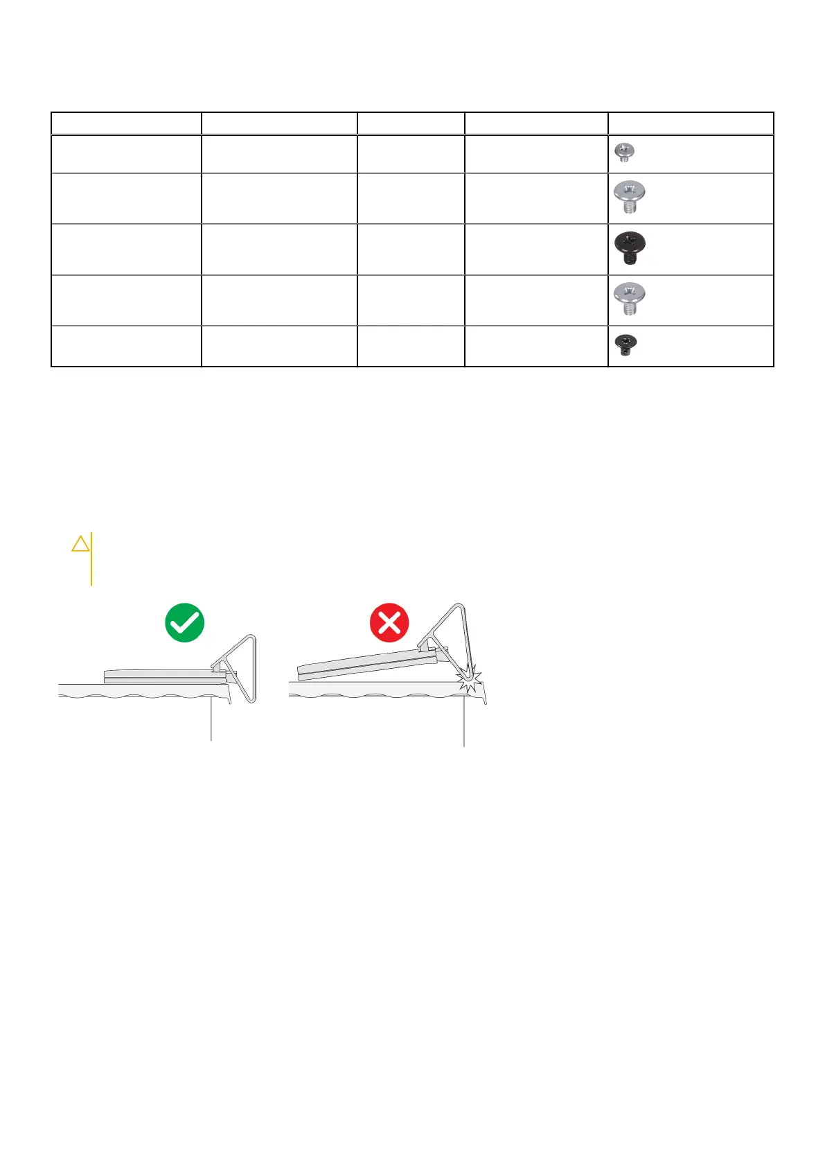
CAUTION:
When servicing the computer, place it on an elevated, clean and flat surface. Place the display
flat on the surface with the stand hanging over the edge. It is recommended to remove the stand to avoid
accidental damage to the computer display during servicing.
About this task
The following image indicates the location of the back cover and provides a visual representation of the removal procedure.
Removing and installing components
11