6. Route the cable properly to prevent the cable from being pinched or crimped.
Steps
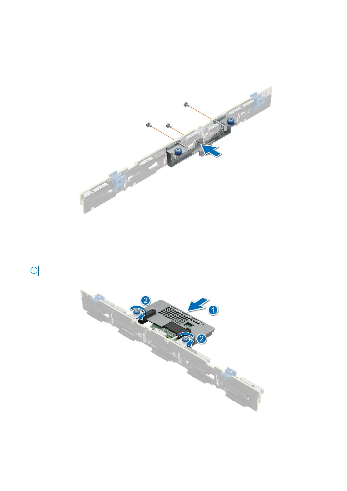
1. Align the slots on the front PERC module bracket with the holes on the drive backplane.
2. Using a Phillips #2 screwdriver, replace the three screws to secure the front PERC module bracket to the drive backplane.
Figure 53. Installing the rear mounting front PERC module bracket
3. Align the connectors on the front PERC module with the connectors on the drive backplane.
4. Slide the front PERC module until the module is connected to the drive backplane.
5. Using a Phillips #2 screwdriver, tighten the captive screws on the front PERC module.
NOTE: The numbers on the image do not depict the exact steps. The numbers are for representation of sequence.
Figure 54. Installing the rear mounting front PERC module
Installing and removing system components
75