Table 41. 10 x 2.5 inch (SAS/SATA w/ 4 Universal) (fPERC11)(continued)
Order From To
3 CTRL_SRC_SB1 (front PERC
controller connector)
BP_DST_SB1 (backplane signal connector)
4 SL2_CPU2_PB1 (signal connector on
system board)
BP_DST_PB2 (backplane signal connector)
5 SL4_CPU1_PB2 (signal connector on
system board)
BP_DST_PA3 (backplane signal connector)
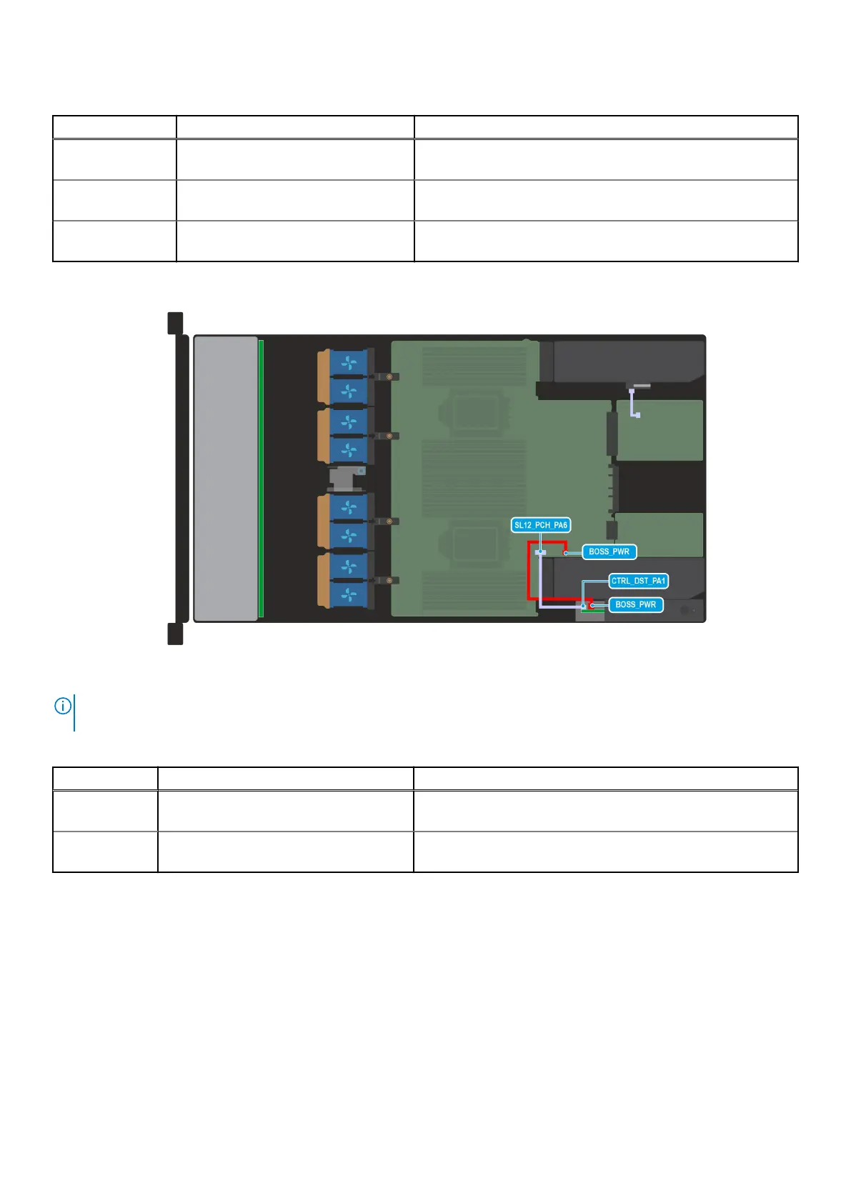
Figure 59. Configuration 3: BOSS-N1 cable
NOTE:
Follow the sequential order as shown in the table to remove the cables, to install the cables follow the reverse
sequential order.
Table 42. BOSS-N1 cable
Order From To
1 BOSS_PWR (BOSS-N1 power connector
on system board)
BOSS_PWR (BOSS-N1 power connector on BOSS-N1 module)
2 SL12_PCH_PA6 (BOSS-N1 signal cable on
the system board)
CTRL_DST_PA1 (BOSS N1 signal cable on the BOSS-N1
module)
System memory
System memory guidelines
The XC Core XC660 system supports DDR5 registered DIMMs (RDIMMs).
Your system memory is organized into eight channels per processor (two memory sockets per channel), 16 memory sockets per
processor and 32 memory sockets per system.
Installing and removing system components
79



 To Next Page