Trigno™ Wireless Biofeedback System
- 11 -
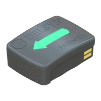
Internal Magnetic Switch
The Trigno Galileo sensors are equipped with an internal magnetic switch which
is used to turn the sensors “on” and to perform RF pairing operations. To
activate the internal magnetic switch, the sensor must be placed on the magnet
lock label located on the Base Station charging cradle. The internal magnetic
switch will only react when the sensors are undocked from the charger or when
the software is performing an RF pairing operation. Exposure to any magnetic
fields outside of these 2 qualifying conditions will be ignored by the sensor. The
internal magnetic switch is a feature which removes the need for a mechanical
button and improves sensor durability and performance.
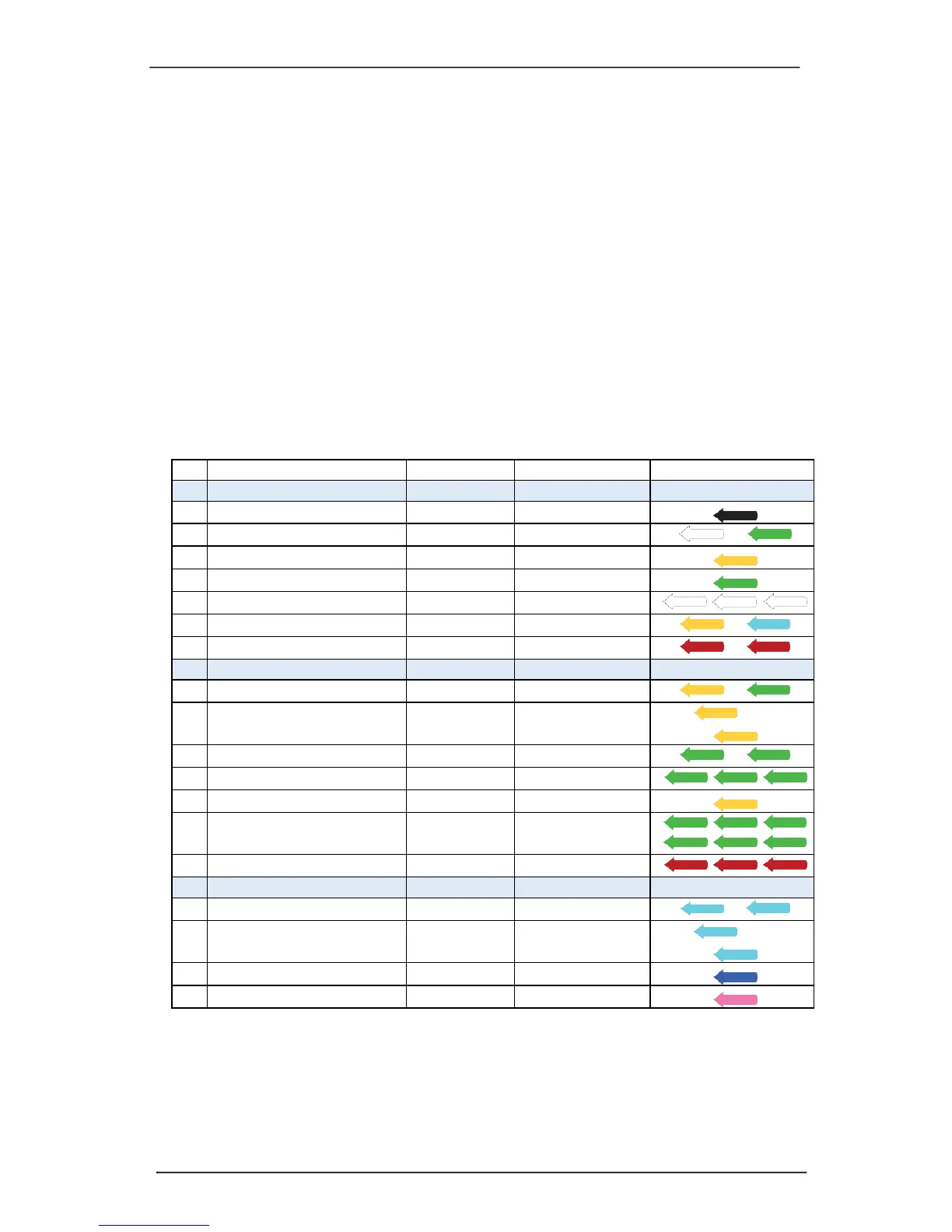
Sensor LED Feedback States
Trigno Galileo sensors indicate their status through various LED Arrow colors
and blink patterns as indicated in the table below. Each of these states is
described in subsequent sections of this User Guide.