Chapter 2 Introduction
17
N O T E :
:KHQWKHEDFNOLJKWRIWKH/&'LVRႇ\RXFDQSUHVVDQ\EXWWRQPHQWLRQHG
above to wake up the display and enable each button function.
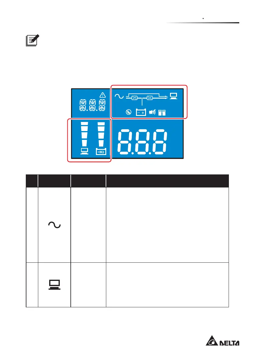
2.5.3 LCD Display
Hz
KW
KVA
AH
MIN
MINV
V
%
IN
SET
IN OUT BATT
RUN TIME
°C
LOAD
TEST
ECO
LOAD 1
LOAD 2
No. Icon Naming Description
1
AC Icon
Indicates the input source status.
1. ON: The AC input is within the acceptable
bypass range.
2. Flashing: The AC input is out of the
DFFHSWDEOHE\SDVVUDQJHEXWLVVWLOOVXႈFLHQW
to let the unit operate in on-line mode.
3. OFF: The AC input is out of the acceptable
E\SDVVUDQJHDQGLVQRWVXႈFLHQWWROHWWKH
unit operate in on-line mode.
2
Load bank
Icon
Indicates the output status.
1. ON (green): There is output to the load bank
1/ load bank 2.
2. OFF: There is no output to the load bank 1/
load bank 2.