Chapter 2 Introduction
19
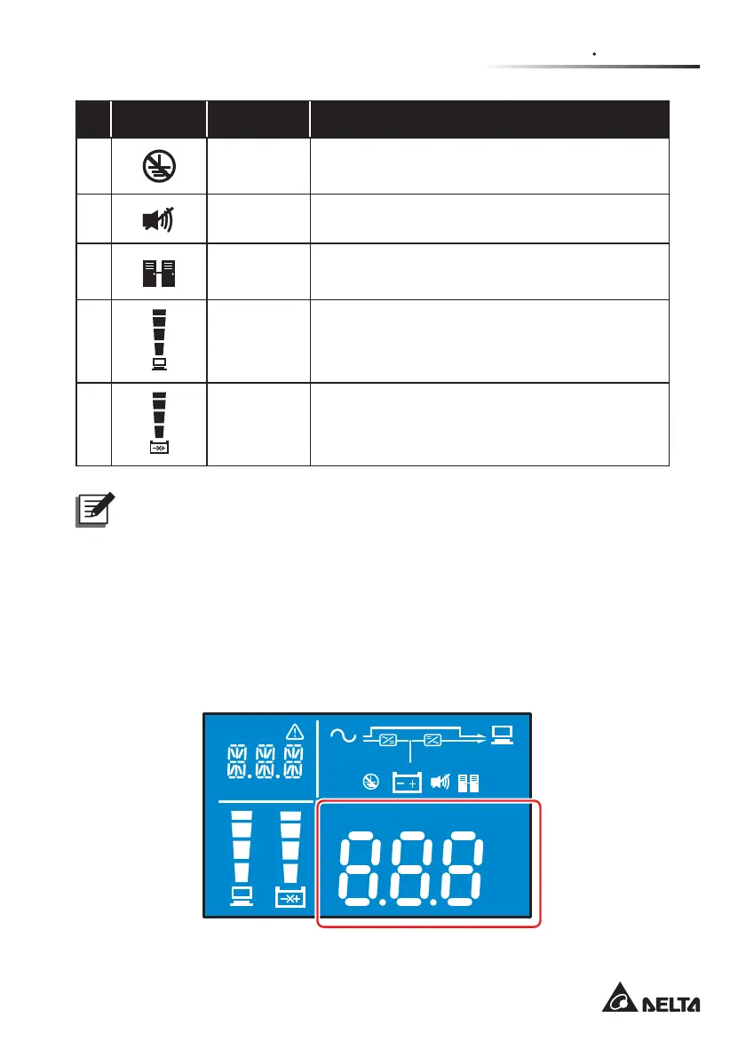
No. Icon Naming Description
13
Site Wiring
Fault Icon
Reserved. This function is only applicable to
120Vac model.
14
Buzzer Icon Illuminates when the buzzer is disabled.
15
Parallel Icon
Reserved. This function is only applicable to
5-10kVA Model.
16
Load Level
Bar Graph
ON: Total capacity (%) of the connected loads*
1
.
17
Battery
Level Bar
Graph
1. ON: The remaining battery capacity (%)*
1
.
2. Flashing: Low battery.
N O T E :
*
1
means that:
1%-25%: the 1st segment will illuminate.
WKH¿UVWWZRVHJPHQWVZLOOLOOXPLQDWH
WKH¿UVWWKUHHVHJPHQWVZLOOLOOXPLQDWH
76%-100%: all segments will illuminate.
2.5.4 7-Segment Display
Hz
KW
KVA
AH
MIN
MINV
V
%
IN
SET
IN OUT BATT
RUN TIME
°C
LOAD
TEST
ECO
LOAD 1
LOAD 2