Chapter 4 Connections
35
4.5 Utility Power Connection
1. Please read 3UHFRQQHFWLRQ:DUQLQJV before connection.
2. Use the provided input cable to connect the UPS and a wall socket that has
an earthing-contact function. If the wall socket does not have an earthing
connection, please ground the UPS via the ground terminal. Please see 5HDU
3DQHO for ground terminal location.
3. After the UPS is connected to the AC utility, the utility will supply power to the
UPS. After that, the fan (at the rear panel) will run, all LEDs and LCD will be on for
about 2-3 seconds. The user can check whether the LEDs and LCD are normal.
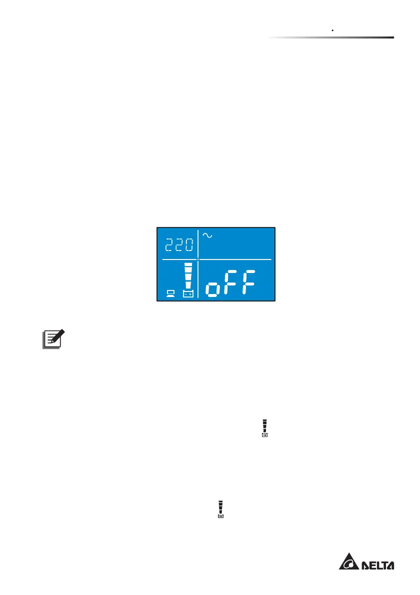
The default setting of the UPS is set in ‘STANDBY mode’ (see )LJXUH).
Please note that once the AC utility supplies power to the UPS, the batteries will
be charged.
)LJXUH,QLWLDO6FUHHQDIWHU8WLOLW\3RZHU&RQQHFWLRQB6WDQGE\0RGH
Hz
KW
KVA
AH
MIN
MINV
V
%
IN
SET
IN OUT BATT
RUN TIME
°C
LOAD
TEST
ECO
LOAD 1
LOAD 2
NOTE :
1. The diagram shown above is for reference only. Actual display depends
on the operation of the UPS.
2. The UPS will charge its internal batteries and the optional Delta external
battery pack (if connected and its DC breaker is turned on) whenever the
UPS is connected to the AC source.
3. It is recommended that you fully charge the UPS’s internal and external
batteries until the Battery Level Bar Graph
shown on the UPS’s LCD
is fully on. If you don’t do this, you may use the UPS immediately but the
‘On-Battery’ runtime might be less than normally expected.
4. If the UPS is going to be out of service or stored for a prolonged period of
time, you must recharge the batteries (internal and external) every three
months and, every time, fully charge the batteries (internal and external)
until the Battery Level Bar Graph
shown on the UPS’s LCD is fully on.
5. The batteries will immediately begin charging upon the availability of the
input power.