Chapter 2 Installation and Wiring|
Revision May 2008, ME14, SW V3.04 2-7
Please use voltage and current within the regulation shown in Appendix A.
When using a GFCI (Ground Fault Circuit Interrupter), select a current sensor with sensitivity of
200mA, and not less than 0.1-second detection time to avoid nuisance tripping.
Do NOT run/stop AC motor drives by turning the power ON/OFF. Run/stop AC motor drives by
RUN/STOP command via control terminals or keypad. If you still need to run/stop AC drives by
turning power ON/OFF, it is recommended to do so only ONCE per hour.
Do NOT connect 3-phase models to a 1-phase power source.
Output terminals for main circuit (U, V, W)
When it needs to install the filter at the output side of terminals U/T1, V/T2, W/T3 on the AC
motor drive. Please use inductance filter. Do not use phase-compensation capacitors or L-C
(Inductance-Capacitance) or R-C (Resistance-Capacitance), unless approved by Delta.
DO NOT connect phase-compensation capacitors or surge absorbers at the output terminals of
AC motor drives.
Use well-insulated motor, suitable for inverter operation.
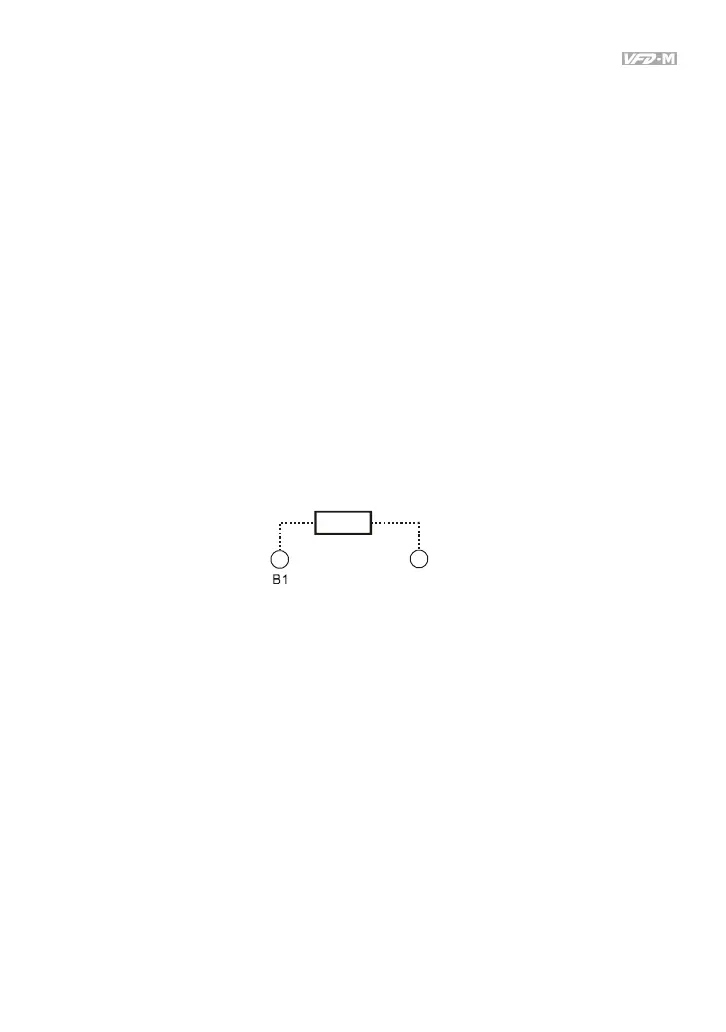
Terminals [B1, B2] for connecting external brake unit
B2
BR
Brake Resistor(optional)
Refer to Appendix B for the use of
special brake resistor
Connect a brake resistor or brake unit in applications with frequent deceleration ramps, short
deceleration time, too low braking torque or requiring increased braking torque.
The AC motor drive has a built-in brake chopper, you can connect the external brake resistor to
the terminals [B1, B2] when needed.
When not used, please leave the terminals [B1, B2] open.