Chapter 4 Parameters|
4-46 Revision May 2008, ME14, SW V3.04
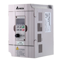
Example 5:
In this example, a 6 Hz (10% of 60 Hz) negative bias is used. This setting is used to provide a noise
margin (1V in this example) in noisy environments. Note that the top frequency is reduced to 54 Hz.
Max.
Output
Freq.
60Hz
Pr.03
0Hz
0V
10V
Factory Settings
Pr.03=60Hz--Max. output Freq.
Pr.48=10.0% -- bias adjustment
Pr.49=1 -- bias polarity
Pr.50=100% -- pot. freq. gain
Pr.51=0 -- Rev. motion disable
in negative bias
Negative
bias 6Hz
1V
54Hz
Hz
0V
10V
24
0
54
Potentiometer Scale
It's 0Hz
within
this
range.
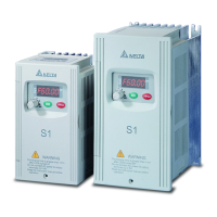
Example 6:
This example also uses negative bias and includes a potentiometer frequency gain to allow the AC
drive to reach the Maximum Output Frequency.
Max.
Output
Freq.
60Hz
Pr.03
0Hz
0V
10V
Factory Settings
Pr.03=60Hz--Max. output Freq.
Pr.48=10%--bias adjustment
Pr.49=1 -- bias polarity
Pr.50=111% -- pot. freq. gain
Pr.51=0 -- REV. motion disable
in negative bias
Negative
bias 6.6Hz
1V
Hz
0V
10V
27
0
60
Potentiometer Scale
It's 0Hz
within
this
range.
Bias adjustment
Calculation of gain
Pr.50=(
10V
9V
)X100%=111%
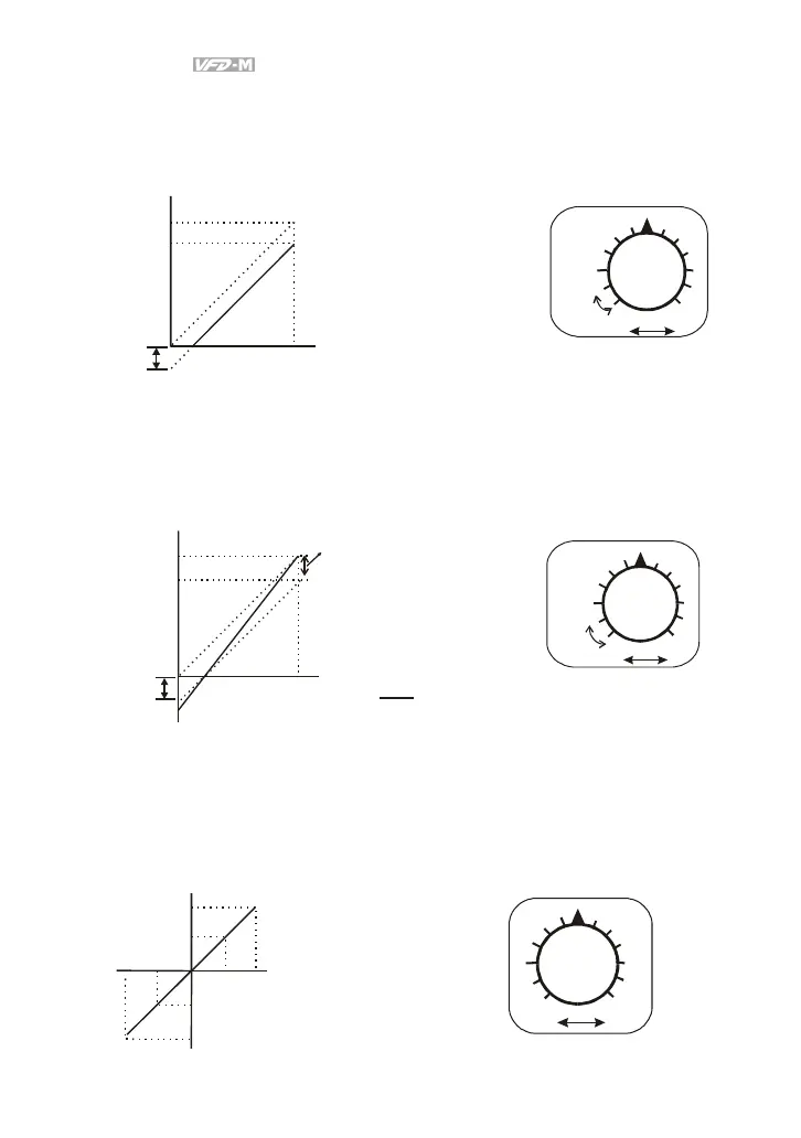
Example 7:
In this example, the potentiometer is programmed to run a motor in forward or reverse direction. The
motor will idle when the potentiometer is set at the scale mid-point. Please note that this adjustment
will disable the external FWD and REV controls.
Max.Output Freq.
Pr.03
Factory Settings
Pr.03=60Hz--Max. output Freq.
Pr.48=50%--bias adjustment
Pr.49=1 -- bias polarity
Pr.50=200% -- pot. freq. gain
Pr.51=1 -- REV motion disable
in negative bias
60Hz
30Hz
0Hz
0V
5V 10V
30Hz
60Hz
REV
FWD
Hz
0V
10V
0
60
60
Potentiometer Scale
REV.
FWD.