8
Fig. 7
Fig. 8
Fig. 9
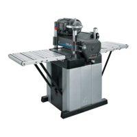
ASSEMBLING
CHIP DEFLECTOR
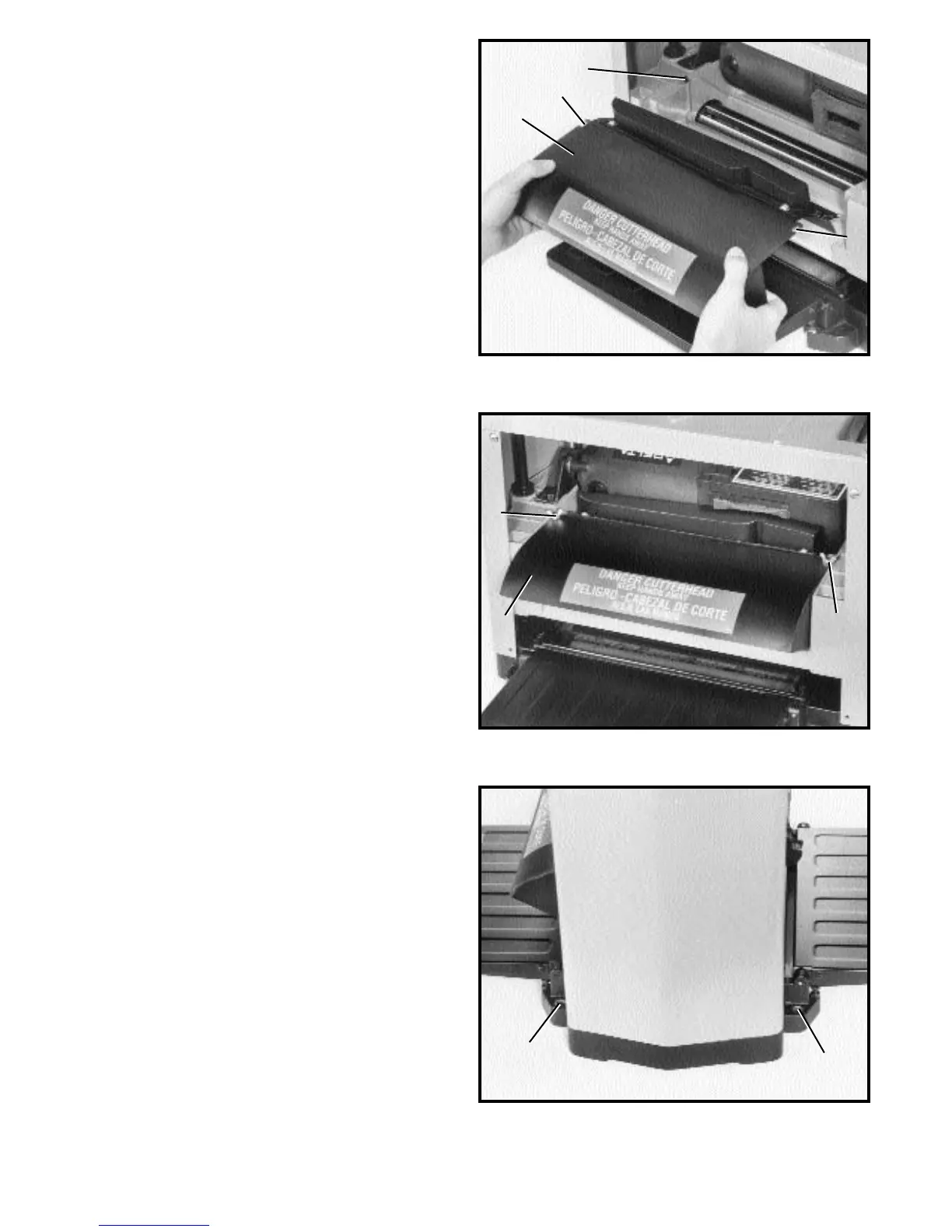
1. Assemble chip deflector (A) Fig. 7, to the planer by
inserting end of chip deflector over the top of the
cutterhead. Make certain the two screws, one of which
is shown at (B) are inserted upward through the two
slots (C) in the chip deflector.
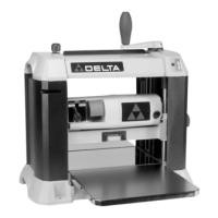
2. Fasten chip deflector (A) Fig. 8, to planer using two
flat washers and wing nuts (D).
FASTENING PLANER TO
SUPPORTING SURFACE
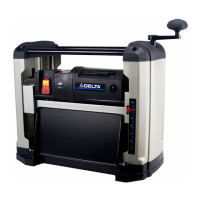
During operation, if there is any tendency for the planer
to tip over, slide or “walk” across the supporting surface,
the planer must be secured to the supporting surface
through the four holes in the base, two of which are
shown at (A) Fig. 9.
D
D
C
C
B
A
A
A
A