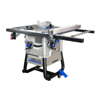
10
1. M8 x 70mm carriage bolt (1)
2. M8 nylock nut (3)
3. M6 x 72mm carriage bolt (4)
4. M6 nut (4)
5. M8 spring wahser (1)
6. Carriage shoulder bolt (2)
7. M6 x 12mm self-tapping bolt (16)
8. 3/16'' hex wrench - T shape (1)
9. 3/16'' hex wrench - L shape (1)
10. 6mm allen hex wrench - L shape (1)
11. 1/4"-20 x 1/2" hex button head screw with 1/4"
spring washer (7)
12. Front rail union plate(1)
13. M5 x16mm shoulder bolt (2)
14. M5 nylock nut (2)
15. 5/16"-18 hex screw (8)
16. M5 x 6mm round head cross screw (1)
17. M8 x16 shoulder bolt (4)
18. M8 nylock nut (4)
19. 5/16-18 x 1 1/8-inch flat head screw (12)
20. 5/16-18 hex flange nut (12)
21. 5/16 lock washer (12)
22. Wire clip: UC-1.5 white (1)
23. Rail alignment gauge (1)
• Do not lift saw without help. Hold it close to your
body while lifting. Keep knees bent and lift with your
legs, not your back.
• Fully assemble saw with leg assembly prior to use.
Leg assembly is an integral and necessary part of the
support structure for this saw.
• Do not modify saw, or create accessories not
recommended for use with this saw.
• Make sure power switch is in “OFF” position before
connecting to power supply.
• Do not connect to power supply until assembly is
complete
• Slotted screwdriver
• Phillips head screwdriver
• 8mm wrench
• 10mm wrench
• 12mm wrench
• 13mm wrench
• 1/2-inch wrench
• 9/16-inch wrench
• 6mm Allen hex wrench
• 5/32-inch Allen wrench
• 3/16-inch Allen wrench
1. Connect the two tube legs by inserting the end
of the left leg (A) into the end of the right leg (B)
as shown in Figure 1. Secure with a M8 x 70mm
carriage bolt and nylock nut and hand tighten.
2. Insert the four open ends of the tube legs into the
leg collars (C) as shown. Secure each leg with a
6mm x 70mm bolt and nut.
3. Attach the back and front leg support panels (D) to
the legs using four M6 x 12mm self-tapping bolts.
A
Saw Front
D
C
B
 Loading...