28
Alignment between the riving knife and blade is set
at the factory and, in most cases, will not need to
be adjusted. However, the alignment should always
be checked after installing blade or riving knife, and
can be adjusted if necessary. If riving knife is out of
alignment with blade, adjustment is needed. Riving
knife must be in alignment front to back (horizontally)
and top to bottom (vertically).
1. Remove the throat plate, blade guard and anti-
kickback assemblies.
2. Raise the blade to full depth of cut and set the tilt
angle to 0°.
3. Raise the riving knife to the through-cutting or
highest position.
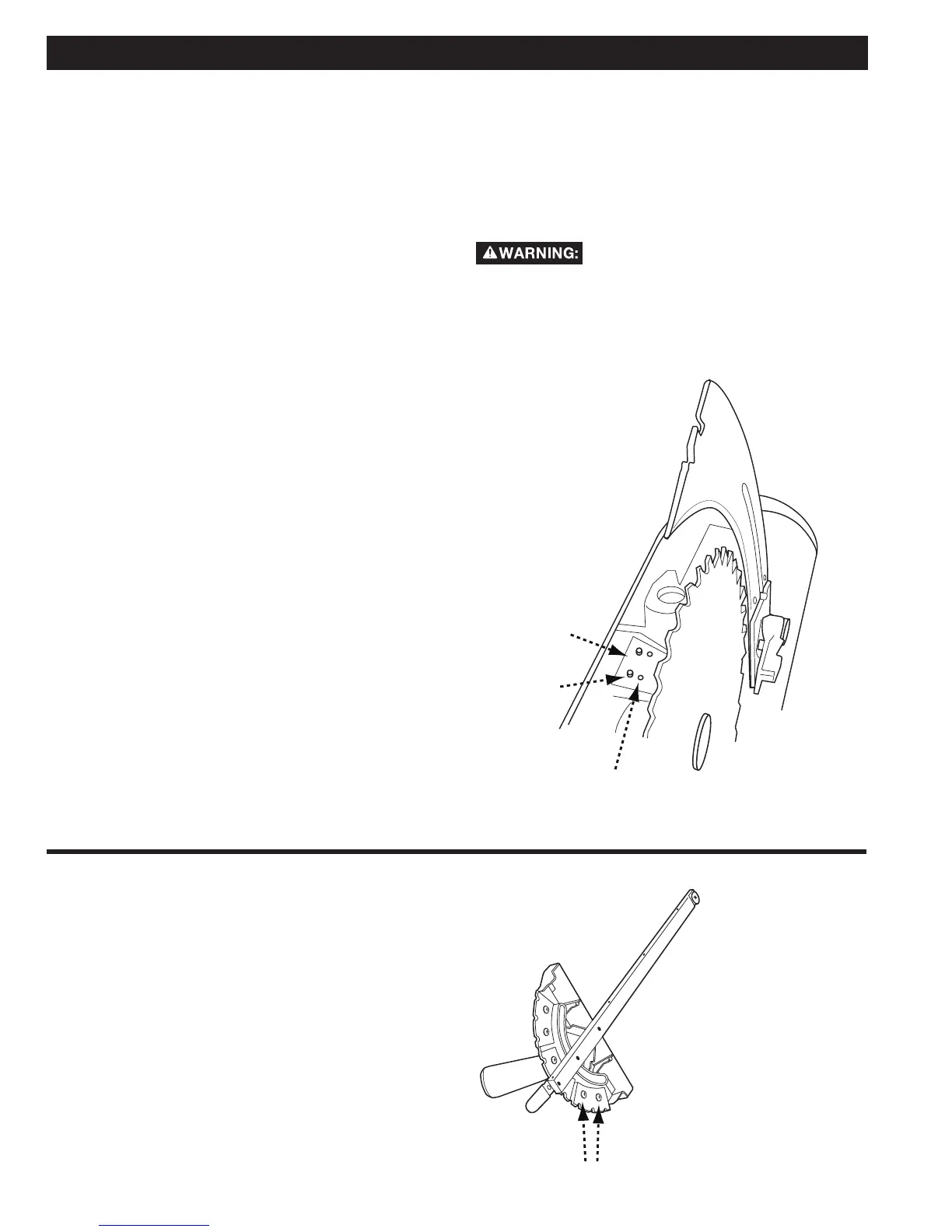
4. Slightly loosen the two socket head cap screws (C).
5. Lay straight edge against the blade face and
riving knife as instructed for checking horizontal
alignment (see Figure 17a, page 18).
6. Adjust the set screws (A) to move the riving knife in
line with the blade according to its position when
you checked the alignment above.
7. Lay the straight edge on the opposite side of the
blade. Both sides of the riving knife should be
within the thickness of the blade body.
8. If it is not possible to align both sides of riving knife
within the thickness of the blade body, you need to
use a different size blade. See Blade Selection on
page 17.
9. Tighten the two socket head cap screws.
10. Place a carpenter’s square on the table, and against
the blade face and riving knife as instructed for
checking vertical alignment (See Figure 17b, page
18). Then verify that the riving knife is perpendicular
to table and in-line with the blade face.
11. If needed, use the set screws (D) to align the riving
knife with blade face and the square.
12. Fully tighten the two socket head cap screws.
13. Replace throat plate, blade guard and anti-kickback
assemblies before use.
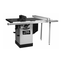
To adjust the index stops for angles other than 90°,
75°, 60°, 45° and 30°:
1. Loosen the miter gauge handle.
2. Loosen the 2 screws for the miter stop segment
for the desired new angle. (A) is shown in Figure
35.
3. Move the stop to proper position.
4. Re-tighten the 2 segment screws and handle.
A
C
B
A