Chapter 2 Specifications and System Configuration
2-78
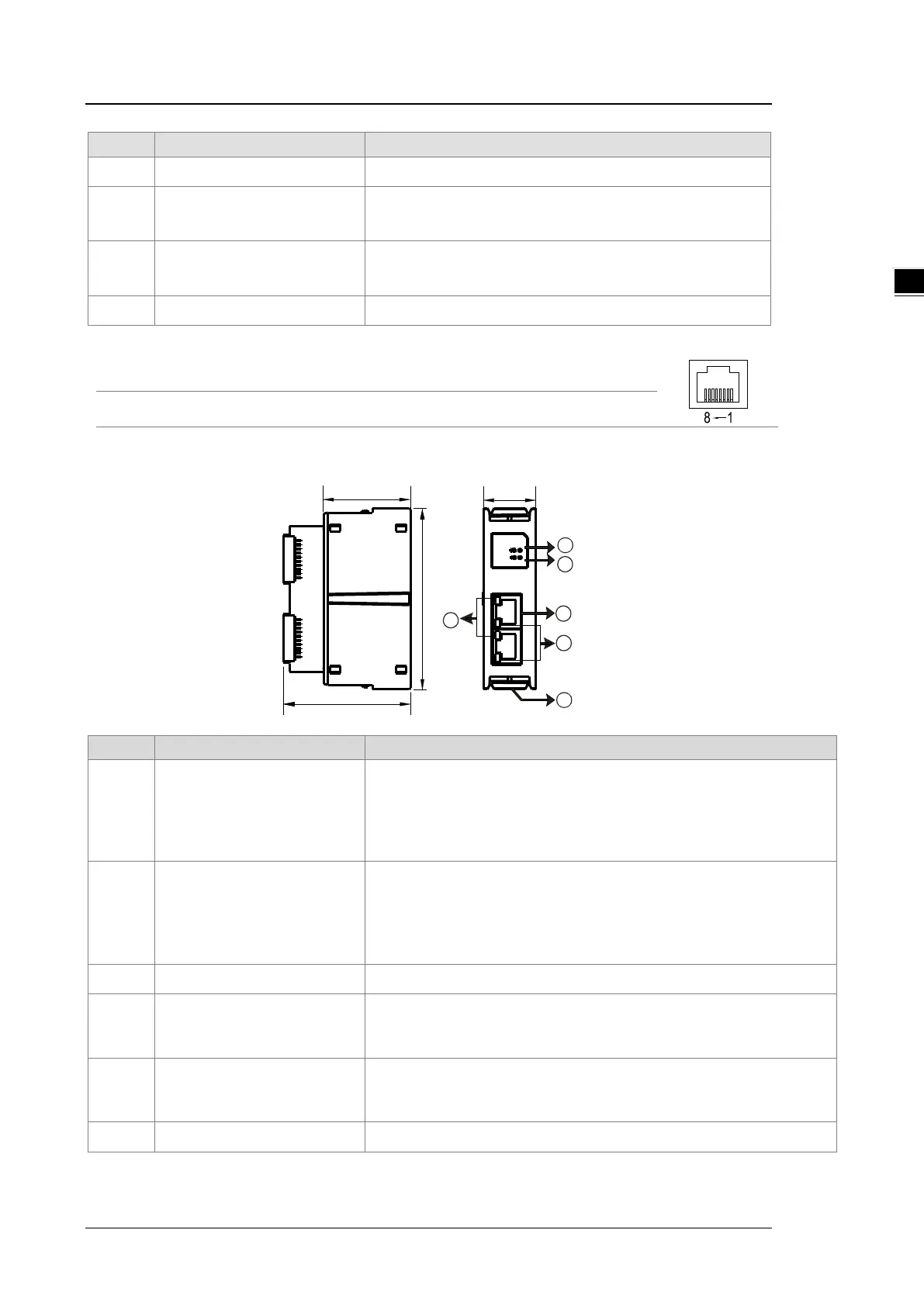
Number Name Description
3 RJ-45 port X1/X2 Use for network connections
4 LINK indicator X1/X2
Indicate the status of Ethernet connection
Green light ON: a network connection is established
OFF: a network connection is not established
5 ACT indicator X1/X2
Indicate the status of Ethernet communication
Orange BLINKING: data transmission
OFF: no data transmission
6 Clip ring Secures AS series
RJ-45 Pin Definition
1 TX+ 2 TX- 3 RX+ 4 N/C
5 N/C 6 RX- 7 N/C 8 N/C
AS-FPFN02
1 SF indicator
System Fail Indicator
Red light ON: an error occurs in the system
Example: the parameters downloaded to the Controller are different from
the actual placement, connecting port 2, instead of connecting to port 1
OFF: no system error
2 BF indicator
Bus Fail Indicator
Red light ON: the connection with PROFINET Controller is OFF.
Red light BLINKING:
the connection is working fine but the communication
with PROFINET Controller is NOT normal.
OFF: the connection with PN-Controller is working fine.
3 RJ-45 port X1/X2 Uses for network connections
4 LINK indicator X1/X2
Indicates the status of Ethernet connection
Green light ON: a network connection is established
OFF: a network connection is not established
5 ACT indicator X1/X2
Indicates the status of Ethernet communication
Orange BLINKING: data transmission
OFF: no data transmission
6 Clip ring Secures AS series
 Loading...